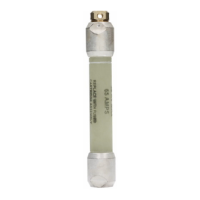
Motor capacitor problem
A problem in the motor capacitor can prevent a regulator
from operating manually or automatically. If the motor
capacitor is in the control box, it can easily be removed
and checked using a voltmeter with a capacitive setting.
To check the motor capacitor if it is not accessible, use the
following steps:
1. Connect a voltmeter from R1 to G.
2. With the control powered up, place the CONTROL
FUNCTION switch on LOCAL MANUAL.
3. Using the RAISE/LOWER switch, give a raise signal.
4. The voltmeter reading should approximate the set
voltage.
5. With the voltmeter still connected between the R1
terminal and G, give a lower signal.
6. The voltmeter should read a capacitive voltage. This
voltage could be somewhere between 160 and 190
Vac.
7. A voltage reading between R1 and G of 0 V or a mV
reading while giving a lower signal is a sign of a bad
capacitor.
8. To double check, place the voltmeter lead between L1
and G.
9. Use the RAISE/LOWER switch, and give a lower
signal.
10. The voltmeter reading should approximate the set
voltage.
11. With the voltmeter still connected to between L1 and
G, give a raise signal.
12. The voltmeter should read a capacitive voltage. This
voltage could be somewhere between 160 and 190
Vac.
13. A voltage reading between L1 and G of 0 V or a mV
reading while giving a lower signal is a sign of a bad
capacitor.
14. If both the raise and lower circuit reads 0 V, or a mV
reading, when there should be a capacitive voltage,
then the motor capacitor is open. The capacitor will
need to be replaced.
15. If 120 Vac is present between R1 and G and L1 and G
when no raise or lower signal is provided, it is a sign of
a shorted motor or capacitor.
Operation counter does not indicate tap change
If the operation counter does not indicate tap changes,
check the following:
1. The voltage signal between TB3-R1 and L1 (or TB2-R3
and L3 is present) should be approximately 120 Vac
when a tap change is made. When this voltage signal
is applied, the control panel operation counter will be
updated.
2. Measure the voltage at R1 and L1 (R3 and L3 if
present) when the tap-changer is given a command
to tap, in manual mode, by the RAISE/LOWER toggle
switch. If the voltage signal is present, the problem is
either in the control connector or the control.
3. If the voltage signal is not present at R1 and L1 (R3 and
L3 if present), the problem could be in the back panel
wiring harness connections at TB1-R1 or L1 (if they are
present), the control cable, junction box connections, or
the holding switch on the tap-changer.
4. Check the voltage signal at TB1-R1 or L1 (if they are
present). If the signal is not present at these points or
at TB3-R1 or L1; keep tracing the signal back through
the components back into the regulator.
Tap position out-of-sync
If the control loses sync with the position indicators (check
FC 12, Present Tap Position), then check:
1. FC 49 Tap-Changer Type against the nameplate on the
regulator. The nameplate indicates what type of tap-
changer is on Eaton's Cooper Power series regulator.
FC 49 must be set for the type of tap-changer (Spring
Drive, Direct Drive, QD8, QD5, QD3).
If the control is installed on a non-Eaton's Cooper
Power series regulator, FC 49 should be set to match
the manufacturer of the unit.
2. The control box ground—An improperly grounded
control box can cause the control to loose tap tracking.
The control box must have a solid ground to the ground
lug on the side of the box, either from the tank ground
pad or earth ground cable.
3. The tap position of the position indicator—When a
control is installed on a unit in the field, the correct tap
position must be entered in the control to match the
position indicator tap position.
Regulator will not tap beyond a certain tap position
If the regulator will not tap beyond a certain tap position,
check the limit switch settings on the position indicator. If
the limits need to be adjusted, adjust upper and lower limits
to allow proper regulation.
If the regulator will not tap beyond a certain position
while in automatic operation, but will beyond this position
manually, check the Soft ADD-AMP settings are FC 79,
FC 175 and FC 176.
If the regulator does not tap beyond tap position 2 in the
lower direction or -2 in raise direction, the problem may
be the internal tap-changer logic switches. Call your Eaton
representative for assistance.
161
INSTALLATION, OPERATION, AND MAINTENANCE INSTRUCTIONS MN225003EN April 2018
CL-7 Voltage Regulator Control

 Loading...


