Page 52 I.L. 17562
PR 0.3 Effective 8/99
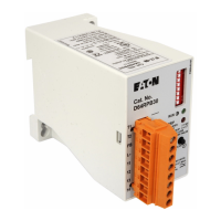
There is one specifically-labeled auxiliary RTD input on the URTD module whose readings can
trigger this particular type of alarm.
5.2.10 Setpoint P2L10, RTD Diagnostic (DIAG ON or DIAG OFF) — Sets the RTD diagnostic
alarm ON or OFF. If set to ON, the relay will alarm on any RTD failure or URTD
communications failure.
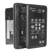
5.3 Page 3, SP TRIP, Setpoints P3L1 to P3L14 — This page contains the setpoints that
configure the trip functions. Any trip function can be turned off as shown in Table 4.3. Start and
run delays are used to block these tripping functions for the set time to avoid nuisance tripping:
• Start delays — begin when the MP-3000 first sees motor current and declares a START.
The start delay completely inhibits operation of the governed function for the set time after
the start. A single setting serves for both tripping and alarming functions.
• Run delays — also known as pickup delays. These delays prevent momentary disturbances
in the system from causing nuisance trips.
• When the motor starts, all of the start delays begin timing. As each start delay expires, the
supervised measurement element is enabled.
• The pickup of a measurement element will begin the timing of its run delay, which must
expire before the relay can actually trip or alarm. Once the run delay timing has begun, the
driving condition must remain for the full run delay time. If the condition goes away and then
returns during run delay timing, the run delay timer resets and begins timing over again.
• Note that the transition of the motor or the MP-3000 relay from START to RUN state has no
bearing on any of these time delays.
Timing Example:
Say the MP-3000 jam trip function (see below) is set for a start delay of 15 seconds and a run
delay of 5 seconds. This motor typically might start and enter the RUN mode in about 5
seconds, but the jam trip start delay setting inhibits any jam detection for 15 seconds regardless
of this. If a jam occurs (causing the current to rise markedly) 12 seconds after the start, the jam
trip function will still be blocked until the 15 second start delay is expired. Then, the jam
measurement element is enabled. It responds at once, but the 5 second jam run delay must
ALSO expire before the relay trips the motor. In this example, if the jam appears, temporarily
clears, and then returns all during the 15-second start delay, there is no effect on tripping. But if
it temporarily clears and returns while the run delay is timing, the run delay resets. The jam must
return for a sustained 5 seconds before a jam trip occurs.
5.3.1 Setpoint P3L1, Ground Fault Trip Level (GFT) — Sets the ground fault trip current
pickup in percent of ground Ct ratio numerator (Ct rated primary current). For example, with a
50:5 ground fault Ct and a setting of 24%, the GFT function will pick up at 24% of 50 A, or 12 A
actual ground fault current in the motor. The start and/or run delays must expire before the trip
occurs.
NOTE
This is the only protective current setting that does not use FLA as the basis for the setting.
5.3.2 Setpoint P3L2, Ground Fault Start Delay (GFSD) — Sets the time from a motor start
until the ground fault trip and alarm functions are enabled, in power cycles. Use this to block
GFT operation until the ground current of power factor correction capacitors decays after a start.

 Loading...


