Do you have a question about the Eaton Cutler-Hammer Digitrip 3000 and is the answer not in the manual?
Discusses essential safety guidelines, warnings, and precautions for safe operation.
Provides an overview of the Digitrip 3000 Protective Relay's capabilities and basic operation.
Details the primary functions, features, and available options of the Digitrip 3000 relay.
Lists the safety and performance standards the Digitrip 3000 Protective Relays comply with.
Covers the relay's core protection functions, testing features, and communication protocols.
Explains the relay's true RMS sensing for accurate current measurement and correlation.
Describes how to set pickup values for various tripping functions like inverse time and short delay.
Details the time delay settings for initiating trip actions based on current levels.
Explains the selection of various inverse time overcurrent curve shapes for coordination.
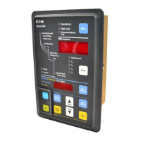
Describes the physical components of the protective relay, including front and rear panels.
Details the pushbuttons, LEDs, and display windows on the relay's front panel for operation.
Discusses the rear panel features, including terminal blocks and DIP switches for configuration.
Provides detailed specifications, compliance, and test summary for the DT3000 and DT3030 models.
Introduces the section on operating the Digitrip 3000 Protective Relay and its functional use.
Explains the sequence of events when power is applied, including self-testing and LED indications.
Guides the user through operating the relay via its front panel controls and displays.
Discusses the relay's ability to provide selective coordination through curve shaping.
Details how to enter and use the program mode to set relay parameters.
Provides flow charts illustrating the sequence for programming the relay settings.
Explains how to perform periodic tests to verify the relay's functional performance.
Describes how the relay communicates data and receives commands via the INCOM network.
Guides on setting the relay's address and baud rate for network communication.
Explains the zone selective interlocking feature for fast fault clearing and coordination.
Outlines the scope of the section covering mounting, wiring, startup, and testing.
Details the steps for preparing the panel and cutting the required openings for mounting.
Provides dimensions and tolerances for preparing the panel cutout for the relay.
Describes the procedure for securely mounting the relay onto the prepared panel.
Provides guidance on configuring a Digitrip 3000 as a replacement for a Digitrip MV.
Explains the wiring requirements and connections for the Digitrip 3000 Protective Relay.
Covers the initial steps and checks before and during the first application of power.
Outlines pre-power application checks, including wiring verification and DIP switch settings.
Describes the procedure for applying control power and verifying initial relay operation.
Covers additional tests and precautions, including dielectric testing.
States that the relay is self-contained and maintenance-free, intended for factory-trained personnel.
Provides guidelines for storing the Digitrip 3000 Protective Relay under specified environmental conditions.
Offers a guide to diagnose and resolve common symptoms and probable causes.
Details the procedural steps required to replace the Digitrip 3000 Protective Relay.
Contains specific time-current curves applicable to the Digitrip 3000 Protective Relay.
Provides the mathematical equations used to define the thermal and ANSI/IEC time-current curves.
Introduces Appendix A, which describes the Drawout Case option for the Digitrip 3000.
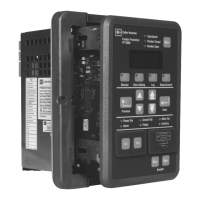
Describes the DT3001 Drawout Relay and its connector specifications.
Details the installation requirements for the Drawout Case, including panel preparation.
Specifies the panel cutout dimensions and requirements for mounting the Drawout Case.
Lists the components included with the DT3001 Drawout Relay for installation.
Provides instructions for mounting the outer case of the DT3001 Drawout Relay onto the panel.
Covers wiring and setup procedures specific to the DT3001 Drawout Relay.
Discusses application considerations, particularly zone selective interlocking for the DT3001.
Explains how to operate the drawout mechanism for inserting and removing the relay.
Provides instructions for correctly inserting the DT3001 relay into its drawout case.
Details the procedure for safely removing the DT3001 relay inner chassis from its drawout case.
Introduces Appendix B, which describes the Dual-Source Power Supply (DSPS) addition to the Digitrip 3000.
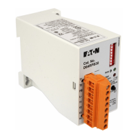
Describes the DT3010/DT3020 DSPS versions and their benefits over standard relays.
Explains how the DSPS functions, including AC power and current powering capabilities.
Covers the installation steps for the Digitrip 3000 with Dual-Source Power Supply.
Details panel preparation, including cutout dimensions for the DSPS unit.
Provides instructions for mounting the Digitrip 3000 with DSPS onto the panel.
Outlines wiring and setup procedures for the Digitrip 3000 with DSPS.
Discusses application considerations for the DSPS, including CT ratios and tripping.
Addresses CT ratio selection and sensitivity requirements for DSPS operation.
Explains how the DSPS handles tripping during facility energization or loss of AC power.
Discusses how the DSPS design helps mitigate issues related to CT saturation.
Presents burden data in ohms and volt-amperes for the DSPS under various conditions.
Provides procedures for testing the proper operation of the Dual-Source Power Supply.
Details steps for testing the DSPS functionality while the unit is in service.
Outlines procedures for performing laboratory bench tests on the DSPS.
| Long Time Delay | Adjustable |
|---|---|
| Short Time Delay | Adjustable |
| Frequency | 50/60 Hz |
| Standards Compliance | UL, CSA, IEC |
| Voltage | 600V AC |
| Voltage Rating | Up to 600 VAC |
| Poles | 3 |
| Communication | Optional |


