I.L. 17562
Page 61
PR 0.3 Effective 8/99
NOTE
The operating specifics of the transition function must be configured on the SP START Page 5,
Setpoints P5L5 to P5L9, if the transition function is set ON here with P10L1.
5.10.1 Setpoint P10L1, Enable transition control output (TRN ON or TRN OFF) - enables
the transition function through output relay AUX2. If ON, the AUX2 relay is activated when the
motor transitions from the START state to the RUN state, and deactivated when the next motor
STOP is declared. Consider MODE 1 versus MODE 2 activation as set by P12L4 below.
5.10.2 Setpoints P10L2 through P10L23, Alarm and Trip assignments to AUX2 - If the
transition function is OFF, then all the other functions for AUX2 are visible. The setpoints are the
same 22 selections as those in the SP AREL page - see Section 5.8. The AUX2 output operates
if any of the selected functions become true.
5.11 Page 11, SP A OUT - configures the operation of the 4-20 mA analog output.
5.11.1 Setpoint P11L1, Analog Output Function (MAX XXXX) — Selects the internal MP-3000
parameter represented by the 4-20 mA analog output. Select one of four choices:
MAX 100 — 100 percent of FLA - proportional to the average of the three-phase current values,
with 100 percent of FLA = 20 mA and zero percent = 4 mA.
MAX 125 — 125 percent of FLA - proportional to the average of the three-phase current values,
with 125 percent of FLA = 20 mA and zero percent = 4 mA.
MAX %I2T — Percent of I
2
T Trip Level - proportional to the percent I
2
T trip level (thermal-model
accumulator bucket), with 100 percent of the I
2
T Trip Level = 20 mA and zero percent = 4 mA.
MAX WRTD — Winding temperature - proportional to the maximum winding RTD temperature
from the URTD module. The winding RTD trip level (setpoint P2L2) = 20 mA and zero degrees C
or 32 degrees F = 4 mA.
5.12 Page 12, SP SYS, Setpoints P12L1 to P12L18 — This page configures overall operation
of the MP-3000.
5.12.1 Setpoint P12L1, Configure Trip Relay Output (TP MODE1 or TP MODE2) — Selects:
• MODE 1 - trip relay is normally de-energized. Energize the trip relay on a trip event.
• MODE 2 - energize the trip relay on power up and de-energize the trip relay on a trip event.
Also called fail-safe mode. This is the factory-set mode.
Keep in mind that each of the output relays has a form c (SPDT) contact set, so that combining
output modes and contact choices gives four logical combinations. Note the key difference in
using Mode 2 with the normally-open contact versus using Mode 1 with the normally-closed
contact. With Mode 2 and a normally-open contact, the external circuit is closed during normal
non-trip operation, and opens for a trip, if the MP-3000 power supply is de-energized, or the
product fails. With Mode 1 and a normally-closed contact, the external circuit opens only for an
overt trip decision, and is maintained when the MP-3000 is de-energized. .
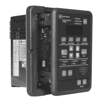
The MP-3000 is normally set for Mode 2 operation of the TRIP and ALARM relays.
5.12.2 Setpoint P12L2, Configure Alarm Relay Output (AL MODE1 or AL MODE2) — Select
Mode 1 or Mode 2 operation of the alarm relay - see 5.12.1 above. The factory default is the
fail-safe MODE 2.

 Loading...


