CircuitProtectionDivision–Electronics(Meters&RelaysBusinessUnit),7/1/2015,version2 Page2of4
Fortechnicalsupportcall800‐809‐2772,Options4,1.Foravailabledocumentationandsoftwarevisitwww.eaton.com/pr.
E‐SERIESCHEATSHEETFOR
FIELD/OPERATIONSPERSONNEL
E‐SeriesRelays
EDR/EMR/ETR/EGR
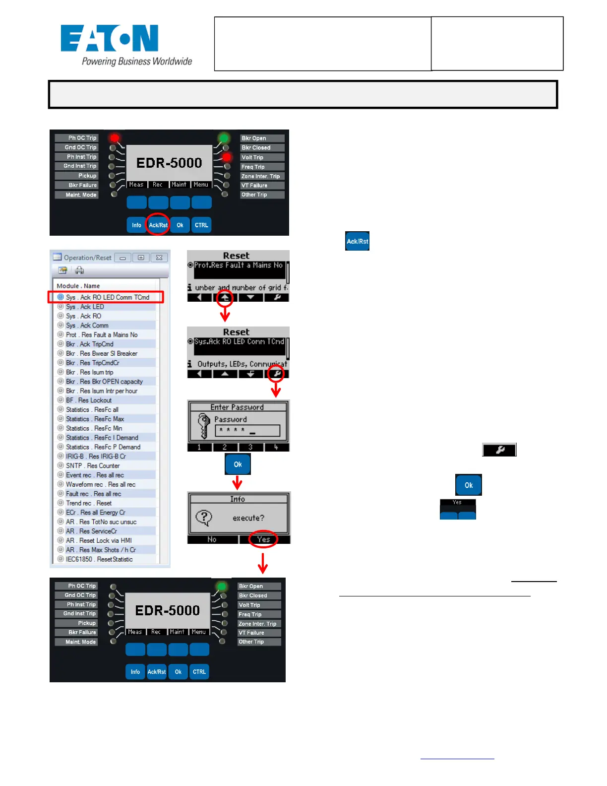
1. It is first recommended to take note of the
specific fault conditions displayed via the
LED’s(seeprocessonpage1,HowtoReview
aFaultCondition)andtheEventRecorder.
2. Press the Acknowledge/Reset soft‐key
()todisplaytheResetmenu.
3. Scroll up or down to find the appropriate
reset command.Generally, the Sys.Ack RO
LEDCommTCmdresetcommandatthetop
isthe desiredchoice;however, caution may
be warranted depending on the relay
protection scheme since this command also
resets any latched relay outputs.A
complete list of available EDR‐5000 reset
actions is shown in the PowerPort‐E
softwareontheleftwhichisidenticaltothe
relayfaceplateselectionlist.
4. Press the wrench soft‐key ( ), then
enter the password (default is 1234), then
press the Oksoft‐key (), then press a
soft‐keyunderYes()toexecutethe
reset.
5. The Relay Outputs, LED’s, Communications,
andTripCommandwillallberesetUNLESSa
trip or pickup condition still exists.If
necessary, review and clear the fault
conditions displayed via the LED’s from the
process on page 1.(i.e. Loss of Utility
voltagemaycauseanundervoltage[27]trip.
Utilityvoltagemustreturntonormalbefore
theconditioncanbeacknowledged/reset.)
HOWTORESETLATCHEDLEDS ANDRELAY OUTPUTS

 Loading...