BE SURE POWER IS DISCONNECTED PRIOR TO INSTALLATION!
FOLLOW NATIONAL, STATE AND LOCAL CODES.
READ THESE INSTRUCTIONS ENTIRELY BEFORE INSTALLATION.
The ECIO-xxx-DN or ECOM-DN Module are convenient and cost-effective DeviceNet interfaces
capable of providing discrete control and monitoring of motor starters, drives, and other devices over
a DeviceNet network. The ECIO-xxx-DN or ECOM-DN is designed to provide the following benefits in
both new and existing installations:
reduced field wiring
greater operator efficiency
ease in system startup and commissioning
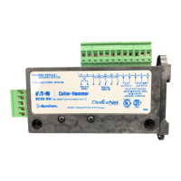
The ECIO-xxx-DN, DeviceNet I/O Module provides four (4) inputs and two (2) AC/DC rated relay
outputs. It can be DIN rail mounted, or mounted directly to a back panel. The ECIO-xxx-DN or
ECOM-DN compact size, ease of wiring and DeviceNet communications capability makes the use of
traditional discrete devices on DeviceNet cost-effective and simple. The ECIO-xxx-DN or ECOM-DN
Module are compatible with Cutler-Hammer’s Model E777 overload relay. It simply connects to the
side of the E777 and, in addition to the extended I/O functions (ECIO-xxx-DN), permits remote
monitoring and control of the E777 over a DeviceNet network. An additional remote reset input is
available on the ECIO-xxx-DN or ECOM-DN to reset a connected E777.
CONNECTIONS
1. Mount the ECIO-xxx-DN or ECOM-DN in a convenient location in a properly rated enclosure.
ECIO-xxx-DN can be mounted to a back panel using screws or can be snapped onto DIN rail.
2. Connect the five DeviceNet wires to the 5-pin connector on the front of the ECIO-xxx-DN or
ECOM-DN Module. 24VDC should be connected to V+ and V-. Connect the other three wires to
CAN High, CAN Low and Shield.
3. ECIO-DN and ECIO-120-DN Connections
NOTE: ECIO-DN inputs are dry contact inputs only, and ECIO-120-DN input require AC
voltage.
ECIO-DN inputs
Connect one side of each input contact to V+ and connect the other side to I1, I2, I3, or I4. The
ECIO-DN must see the V+ voltage to indicate the input is closed.
ECIO-120-DN inputs
Connect L1 of an AC source to C (AC common) connect L2 of an AC source to each input contact,
Connect the other side of each input contact to I1, I2, I3, or I4. The ECIO-120-DN must see AC
voltage to indicate the input is closed.
4. The MNS LED indicates communication is established between the ECIO-xxx-DN and the
DeviceNet master, and OLC indicates communication is established with the E777 overload (if
installed).
5. OUTPUT A, OUTPUT B and the REMOTE RESET connections are made to the top green
connector of the ECIO-xxx-DN Module.
INSTALLATION INSTRUCTIONS FOR
MODEL ECIO-DN, ECIO-120-DN, ECOM-DN