3
11/06
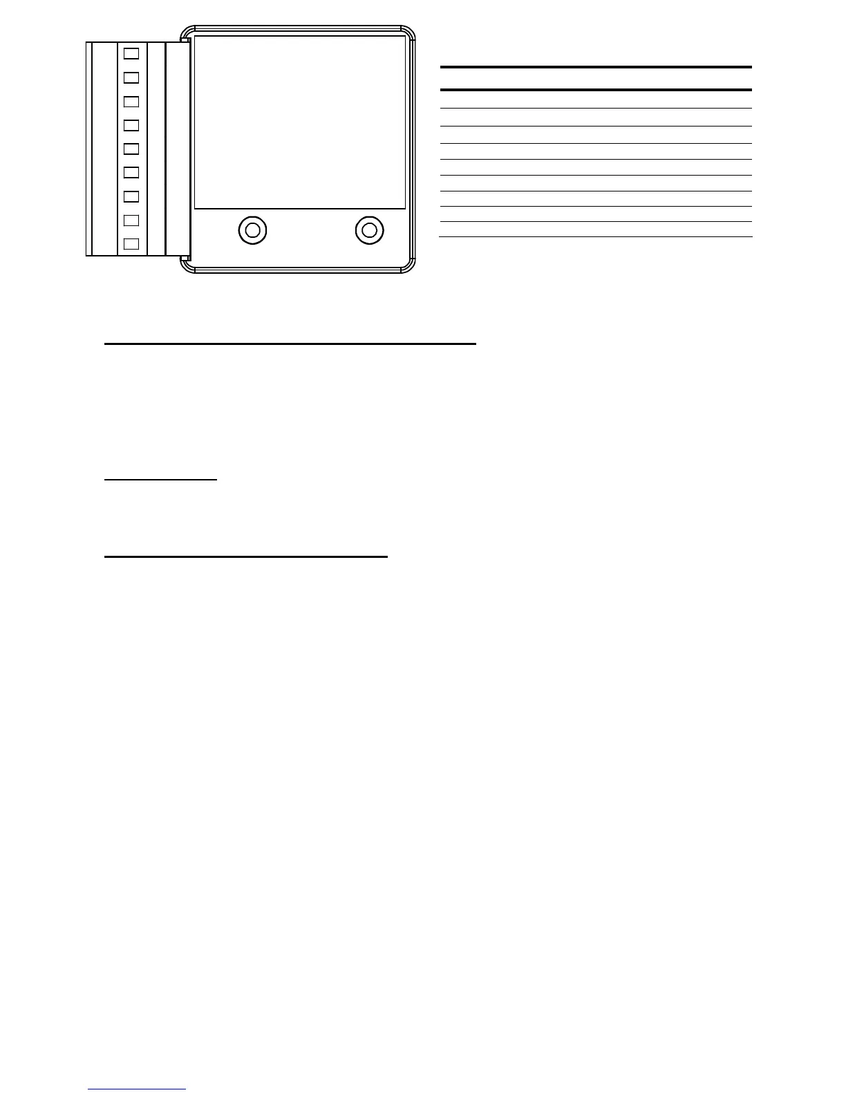
Figure 3-ECOM-DN Typical Wiring Diagram
DIAGNOSTIC INDICATOR LIGHTS (ECIO-XXX-DN Only)
The unit is energized when power is applied between V+ and V- on the connector. The MNS and
OLC lights will flash until communication is established. The MNS communication status indicator
light will come on steady when a DeviceNet master is communicating with the unit. The OLC
communications status indicator light will come on steady when it is communicating to an E777
overload relay (optional).
REMOTE RESET
The R terminals can be connected to a normally open pushbutton to remotely reset a connected
E777 overload.
DEVICENET NETWORK CONFIGURATION
Cable Routing
Follow these general cable-routing guidelines:
• Avoid areas of high temperature, moisture, vibration, or other mechanical stress.
• Secure the cable where necessary to prevent damage.
• Use cable ducts, raceways, or other structures to protect the cable.
• Never route cables over or around sharp edges.
• Avoid sources of electrical interference that can induce noise into the cable. Use the maximum
practicable separation from such sources. Run communication cables at right angles to power
cables.
• Maintain a minimum separation of 3.3 ft. (1m) from the following equipment:
o air conditioners and large blowers
o elevators and escalators
o radios and televisions
o intercom and security systems
o fluorescent, incandescent, and neon lighting fixtures
• Maintain a minimum separation of 10 ft. (3m) from the following equipment:
o Line and motor power wiring
o Transformers
o Generators
o Alternators
TABLE 2-ECOM-DN Terminals
Terminal Designations Description
V+
DeviceNet Power
H
Signal High
S
Shield Tie Point
L
Signal Low
V-
DeviceNet Common
R Remote Reset Switch
R Remote Reset Switch
G Do not use
P Do not use
V+
H
S
L
V-
R
R
G
P