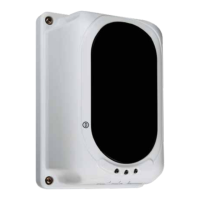
The EF-CBD130 is a conventional reflective beam detector designed for use with Eaton's range of conventional fire systems. It operates on the principle of reflective infrared beam obscuration, detecting smoke by measuring the decrease in received infrared light caused by smoke particles. When the infrared beam is obscured by smoke, the detector notifies the fire alarm panel.
Function Description:
The EF-CBD130 continuously emits an infrared light beam towards a reflector. In the event of a fire, smoke entering the beam path absorbs or scatters some of the light, reducing the received signal. The detector's microprocessor decodes these signals and compares them against a pre-programmed algorithm to determine if a fire condition exists. Upon detecting a fire, it activates corresponding relays and LED indicators. The device is designed for single-ended operation, meaning the detector unit houses both the transmitter and receiver, and a reflector is used to return the beam. It features a self-diagnosis function to monitor for internal faults within its emitting, receiving, and amplifying circuits, generating fault information if issues arise. Automatic compensation for factors like dust contamination, positional movement, and aging of the transmitter helps maintain normal operation by adjusting for weakening received signals. A fault signal is generated if dust levels on the lens and reflector surface reach a critical point where light compensation limits are exceeded.
Important Technical Specifications:
- Part Number: EF-CBD130
- Standard Compliance: LPCB Certification, EN 54-12:2015, BS 5839 Part 1:2017
- Operating Voltage: 20 V to 28 V DC
- Current Parameters:
- Standby: 23mA
- Commissioning: 56mA
- Alarm: 33mA
- Beam Sensor Sensitivity (via Encoder):
- Level 1: 2.6 dB High Sensitivity
- Level 2: 3.8 dB Medium Sensitivity
- Level 3: 5.8 dB Low Sensitivity
- Beam Pathway Length (via Encoder):
- Span 1: 8 to 20 meters (Limited Path)
- Span 2: 20 to 40 meters (Short Path)
- Span 3: 40 to 70 meters (Normal Path)
- Span 4: 70 to 100 meters (Long Path)
- Beam Path Angle: ±0.4° Directional (average of left and right deflection angles)
- Alignment Guide: Laser Beam Pointer
- Digital Display Guide: Nixie Tube
- LED Indicator Guide:
- Red: Fire
- Yellow: Fault
- Green: Alignment
- Reset Time: Less than 2 seconds
- Relay Capacity (Fire & Fault): Normally Open & Close/ 2.0 A; 30 VDC
- Material / Colour: ABS / White
- Dimension / Weight: L:190.87 x W:126.87 x H:91.96 mm / 440 gm (0.130 Kg with base)
- Operating Temperature: -10°C to +50°C
- Ingress Protection Rating: IP30 (IP66 glue seal for permanent fixing, not EN54-12 approved)
- Humidity: 0 to 95% Relative Humidity, Non-condensing
Usage Features:
- Easy Alignment: Features a built-in laser pointer and digital display for intuitive alignment. The laser pointer marks the exact reflector location, and the digital display shows light intensity for optimal adjustment.
- Adjustable Operational Ranges: Four selectable ranges from 8 to 100 meters (8-20m, 20-40m, 40-70m, 70-100m) via an encoder.
- Adjustable Sensitivity: Three user-programmable sensitivity settings (2.6dB, 3.8dB, 5.8dB) to suit specific environmental requirements.
- Microprocessor Control: Built-in microprocessor for intelligent signal processing and fault monitoring.
- Relay Interfacing: Provides Fire and Fault interfacing relays for connection to fire alarm panels.
- Application Suitability: Ideal for high ceilings and wide areas such as warehouses, large stores, shopping malls, leisure centers, exhibition halls, hotel lobbies, printing houses, garment factories, museums, and prisons, including environments with slight smoke particles or corrosive gas.
- Mounting Flexibility: Requires one reflector for distances between 8m and 40m, and four reflectors for distances between 40m and 100m.
- Commissioning Process: A guided commissioning process involves:
- Entering commissioning mode using a magnetic tool.
- Sightline alignment using the laser pointer and horizontal/vertical adjustment wheels.
- Adjusting signal intensity to an acceptable level (indicated by a digital display from 1 to 8, with 8 being optimal, and 2 or 3 acceptable for long paths).
- Finalizing installation by replacing the cover and exiting commissioning mode with the magnetic tool.
- Testing fire signals using opaque/translucent material to cover half the detector, observing the Red LED and relay latching.
- Testing fault signals using opaque material to cover one half of the detector, observing the Yellow LED and relay latching.
- Resetting: The detector automatically resets to normal status if an opaque material is removed within 15 seconds. If maintained for more than 15 seconds, a fire signal is registered, requiring a power cycle of at least 2 seconds to reset.
Maintenance Features:
- Regular Maintenance: Recommended semi-annually or quarterly depending on site conditions.
- Cleaning: Use a damp cloth to clean the detector; avoid cleaning chemicals that may leave residue on electronic parts or the smoke sensor.
- Troubleshooting Guide: Provides guidance for common issues:
- Faults after commissioning: May indicate a dirty detector, moved line of sight, or improper initial commissioning. Troubleshooting involves conducting maintenance or re-commissioning.
- Unable to commission: Could be due to a non-working transmit/receive diode or a damaged reed switch, requiring component replacement.
- Persistent fire signal: Suggests vibration or electro-static discharge issues, or incorrect pre-set after commissioning, requiring re-commissioning.
- Fire signal cannot be cleared: Indicates obscuration on the optical pathway or a changed optical pathway angle, necessitating re-commissioning and realignment.
- Safety Precautions: Emphasizes disabling the detector on the control panel before maintenance to prevent false alarms and warns against adjusting or modifying the detector, as this could affect performance and void the warranty.
- Lifespan and Testing: The detector contains electronic parts that can fail over time. It is recommended to test the beam detector at least every 6 months in accordance with national codes and laws. Any failing components must be repaired or replaced immediately.