Battery charging
If it is not possible to charge the battery with the control’s
built-in charger, a KME5-60-1 (120 VAC) portable bench
type battery charger kit is available, which includes the
KA43ME7001 Battery Charger and the KME5-325-1 Adapter
Cable. Refer to S280-79-14 KA43ME7001 Portable Lead Acid
Battery Charger Instructions for additional information.
IMPORTANT
Do not attempt to charge a lead acid battery below 2
VDC with the KA43ME7001 charger. The charger requires
a minimal voltage to sense a battery is connected.
If the lead acid battery is below 19 VDC for over 2 days,
replace the battery. The expired battery should be
disposed of in an environmentally responsible manner.
Consult local regulations for proper battery disposal.
Charge the battery with a KA43ME7001 (120 VAC) portable
charger as applicable:
Form 4D Pole-Mount Recloser Control (Standard
Capacity) – Connect the battery directly to the
KA43ME7001 charger. The charger continuously
monitors the battery voltage.
Form 4D Pole-Mount Recloser Control (High Capacity)–
Use adapter KME5-325-1 to connect the two 12 volt
batteries to the KA43ME7001 charger.
IMPORTANT
Never connect a single 12 volt battery to the
KA43ME7001 charger. Use adapter KME5-325-1 with the
battery assembly when connecting the charger to the
two 12 volt batteries.
ote:N A yellow LED indicator on the body of the charger
illuminates when charging. A green LED indicator
illuminates when the charge is complete.
The charger senses when the battery voltage reaches
2.27 volts per cell, then the charge rate reduces to maintain
a trickle charge.
The yellow LED flickers to indicate the battery has reached a
full charge. This process can take up to 24 hours.
Refer to Table 17 for additional battery charging accessories.
Table 17. Battery charging accessories
Description Catalog number
120 VAC Battery charger for spare batteries . . . . KME5-60-1
Form 4D battery replacement procedure
The 24 VDC control battery has a life expectancy of four
years. It is recommended that the battery(s) be replaced
after four years or if the battery(s) fails a battery test (after
sufficient recharge time) - whichever occurs first.
ote:N Battery life is decreased at higher temperatures.
This procedure applies to a control with one or two
batteries.
1. Follow all locally approved safety procedures.
2. Disconnect the control wiring to the battery(s) that will
be replaced (Figure 44).
Figure 44. Battery connector
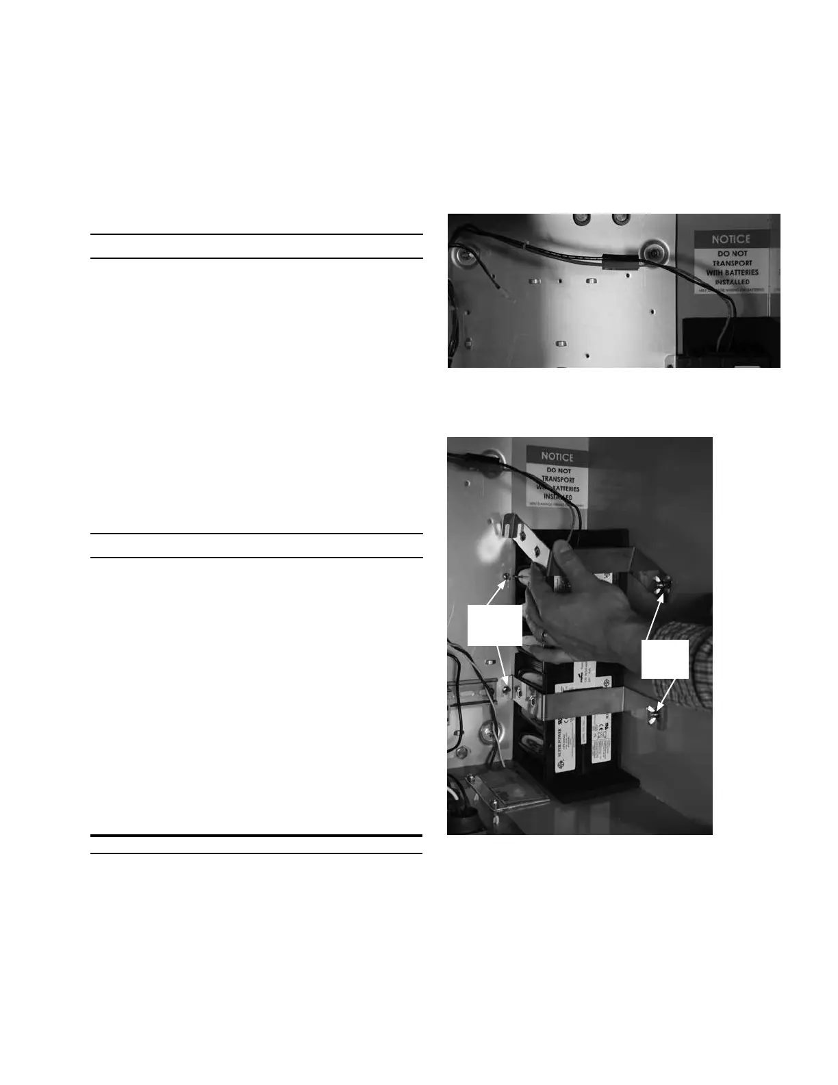
3. Loosen, but do not remove, the battery bracket two wing
nuts located to the front-right of battery (Figure 45).
Thumb
Screws
Wing
Nuts
Figure 45. Loosen and lift battery bracket
4. Loosen, but do not remove, the two thumb screws for
the battery brackets [located to the back-left of battery]
(Figure 45).
5. Push up on the open notch end of the top battery
bracket to release one end as shown in Figure 45.
(continued on next page)
43OPERATION INSTRUCTIONS MN280049EN September 2017
Form 4D Microprocessor-based pole-mount recloser control installation and operation instructions

 Loading...


