7
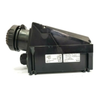
Explosion protected plug and socket system 16 A,
3-pole, 4-pole, 5-pole, GHG 511
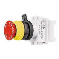
2 Safety instructions GHG 511
plugs and sockets
a
They are not suitable for Zone 0
and Zone 20 hazardous areas.
The temperature class and
explosion group marked on the apparatus
shall be observed.
The electrical connection of the device may
only be carried out by skilled staff
(IEC/EN 60079-14).
Modifications to the plugs and sockets or
changes of their design are not permitted.
They shall be used for their intended
purpose and in perfect and clean condition.
The requirements of the IEC/EN 60079-31
regarding excessive dust deposits and
temperature to be considered from the user.
To ensure adherence to the temperature
class stated on the type label of the
apparatus, the permissible ambient
temperature, the rated terminal cross
section and the self heating of the apparatus
that is mainly due to the power dissipation
shall be taken into account (test criterion for
the self heating is an overload of 10%).
Prior to taking the plugs and sockets into
operation, they will have to be checked in
accordance with the instruction as per
section 6.
The sockets may only be used with the
associated Cooper Crouse-Hinds plugs in
undamaged condition.
The interlocking switch of the socket is
mechanically secured and cannot be
connected without plug.
The plugs GHG 543/531 can further on be
inserted with the sockets of the series
GHG 543/GHG531.
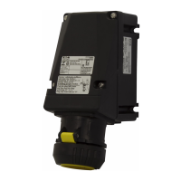
Flange sockets may only be used in
protective enclosure or apparatus that have
been certified for the respective application.
Observe the national safety rules and
regulations for prevention of accidents as
well as the safety instructions included in
these operating instructions and set in
italics the same as this text!
1 Technical data
ATEX type examination certificate / IECEx type examination certificate:
Wall socket GHG 511 4. PTB 99 ATEX 1039 IECEx BKI 04.0002
Plug GHG 511 7. PTB 99 ATEX 1039 IECEx BKI 04.0002
Coupler GHG 511 3. PTB 99 ATEX 1039 IECEx BKI 04.0002
Flange socket GHG 511 8.
BVS 15 ATEX E 101 U IECEx BVS 15.0088U
Plug GHG 543 2. PTB 99 ATEX 1039 IECEx BKI 04.0002
Plug GHG 531 7. PTB 99 ATEX 1039 IECEx BKI 04.0002
Marking acc. to 2014/34/EU and standard:
EN 60079-0
D
II 2 G Ex de [ia] II C T6*
bzw. T5
D
II 2 D Ex tD A21 IP 66 T 80 °C
Flange socket GHG 511 8
D
II 2 G Ex db eb IIC/IIB Gb
D
II 2 D Ex tb IIIC Db
Marking acc.:
IEC60079-0
Ex de [ia] II C T6* bzw. T5
Ex tD A21 IP 66 T 80 °C
Flange socket GHG 511 8
Ex db eb IIC/IIB Gb
Ex tb IIIC Db
Rated voltage:
GHG 511 - 3-pole up to 415 V, 50/60 Hz
GHG 511 - 4-pole up to 690 V, 50/60 Hz
GHG 511 - 5-pole up to 690 V, 50/60 Hz
Plug GHG 543 2. up to 250 V, 50/60 Hz
Plug GHG 531 7. up to 690 V, 50/60 Hz
(Special voltages and various contact-marking are possible on request.)
Rated curret: max. 16 A
Back-up fuse: GHG 511 GHG 543/531
without thermal protection 25A 16 A
with thermal protection 35A gL/gG 32A gL/gG
Switching capacity AC 3
3-pole: 250 V/16 A
Switching capacity AC 3
4-pole: 400 V/16 A
Switching capacity AC 3
5-pole: 500 V/16 A
* Perm. ambient temperature: 16 A (T6) -20 °C to +40 °C (catalogue version)
16 A (T6) -20 °C to +50 °C
15 A (T6) -20 °C to +55 °C
(Special versions permit deviating temperatures.)
Perm. storage temperature in original packing: -20 °C to +55 °C
Protection category acc. to EN/IEC 60529 IP 66 (catalogue version)**
**with closed and secured hinged cover as well as combinations properly plugged together.
Attention! When the Plugs GHG 543/531 is insert with sockets of the series GHG 511, the "IP"
protection category of the combina- tion is reduced to the minimum protection category "IP 54".
Insulation class acc. to IEC/EN 61140: II - is complied with by devices
Cable entry: (catalogue version)
Wall socket 2 x M25 1 x M25 + 1 x screwed blanking plug
Suitable cables and test torques of the pressure
screw (Ømm/Nm)
M20 M25 M32
Seal 1+2+3
min.
max.
(1)(2)
5.5/1,5
7.0/1,0
8.0/1,5
10.0/2.0
Seal 1+2
min.
max.
(1)(2)
7.0/1,5
9.0/1.4
10.0/2.3
13.0/2.6
14.0/3.0
17.0/4.0
Seal 1
min.
max.
(2)
9.5/1,0
13.0/1.7
13.5/1.3
17.5/2.3
17.5/1.5
21.0/1.3
Test torque for screw in thread cable entry (Nm) 2.7 3.0 5.0
(1)
The tests of clamping ranges and torque values were performed with metal mandrel. The clamping range
can vary by using cables with different manufacturing tolerances and material properties. Please use the
combination of sealing 1 + 2 + 3 for the intermediate region.
(2)
When selecting the seal rubber, ensure that the cap nut can be tightened when carrying out any future
maintenance work on the cable entry.
Plug / Coupler 3-pole Ø 8 - 19 mm
4-pole Ø 8 - 21 mm
5-pole Ø 12 - 21 mm
Plug GHG 543/531 Ø 9 - 17 mm
Supply terminal Cross section Stripped wire length
Wall socket/flange socket GHG 511
2 x 1.5 - 4.0 mm
2
10 mm
Coupler GHG 511
2 x 1.5 - 4.0 mm
2
10 mm
Plug GHG 511
1 x 1.0 - 2.5 mm
2
9 mm
Plug GHG 543/531
1 x 1.0 - 4.0 mm
2
8 mm
Test torques:
Cover screws 2.5 Nm
Terminals 2.5 Nm
Terminals plug 1.5 Nm
Self-cutting screws size 4 1.6 Nm
(Page 15: Fig. 3; Pos. 3)
Locking screw for pressure piece GHG 54 1.6 Nm
GB
 Loading...