Type VSA12, VSA16 and VSA20/800 maintenance instructions
8MAINTENANCE INSTRUCTIONS MN280064EN October 2017
The major components of the operating mechanism are
easily accessible without need to remove the mechanism.
However, if necessary, the complete operating mechanism
can be removed from the operating cabinet as a unit.
Mechanism removal
1. Remove fused pullout switch to de-energize AC power
source to operator mechanism.
2. Make sure recloser contacts are open; manually
operate mechanism, if necessary, until contact position
indicator reads OPEN and closing spring status indicator
reads SPRINGS DISCHARGED.
3. Remove screws attaching auxiliary switch to
mechanism frame. Remove auxiliary switch.
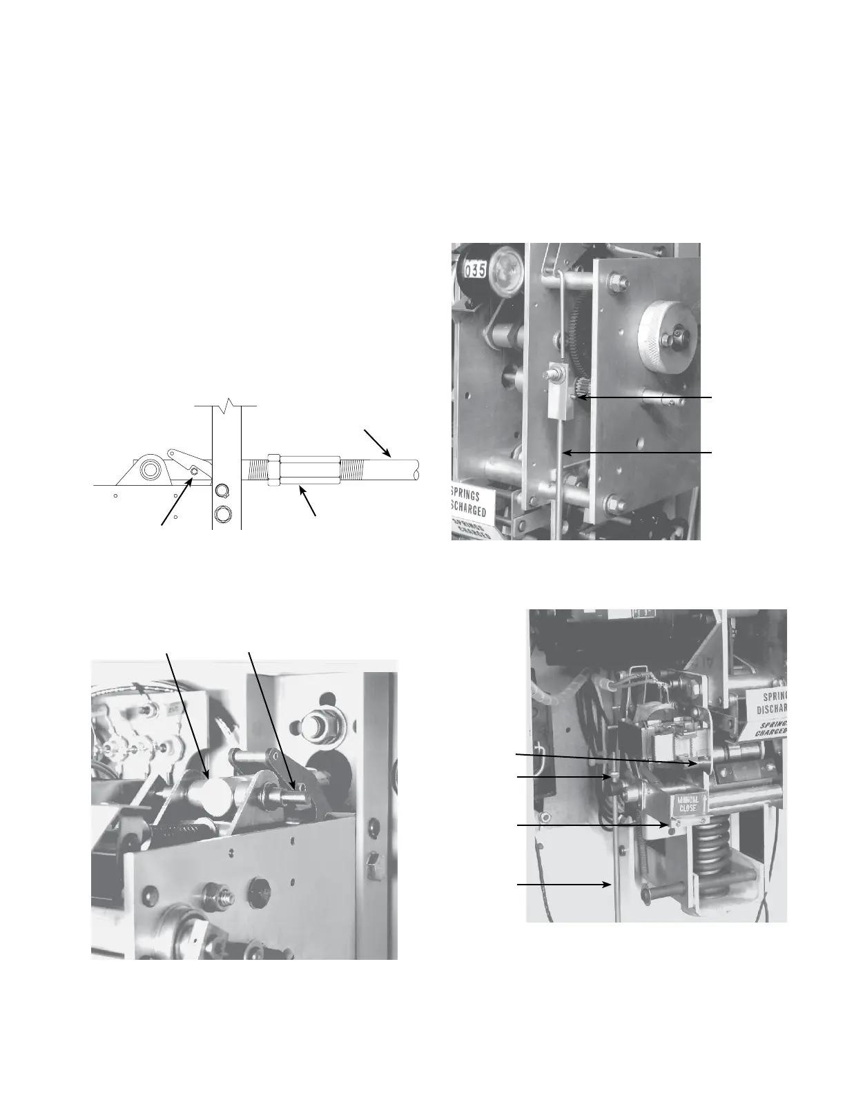
4. Loosen operating bar turnbuckle assembly, inside
interrupter housing, see Figure 10.
Operating bar
assembly
Turnbuckle
assembly
Roll pin
Figure 10. Turnbuckle assembly
5. Remove link pin that attaches operating mechanism to
operating bar assembly, Figure 11.
Operating bar
assembly Link pin
Figure 11. Location of link pin
6. Turn operating bar clockwise 90 degrees to isengage
roll pin from anti-bounce latch.
7. Unplug wiring harness from panel board on the back of
the cabinet.
8. Remove trip reset knob and front plate, remove cotter-
pin to disconnect external trip pullring from threaded
pin on trip link, Figure 12.
Cotter pin
Trip pullring
Figure 12. Removal of external trip pullring
9. Disconnect external quick-close pull hook by removing
attaching stop nut, Figure 13.
Spacer
Stop nut
Manual
close lever
External
quick close
pullring
Figure 13. Attachment of external quick-close pullring

 Loading...


