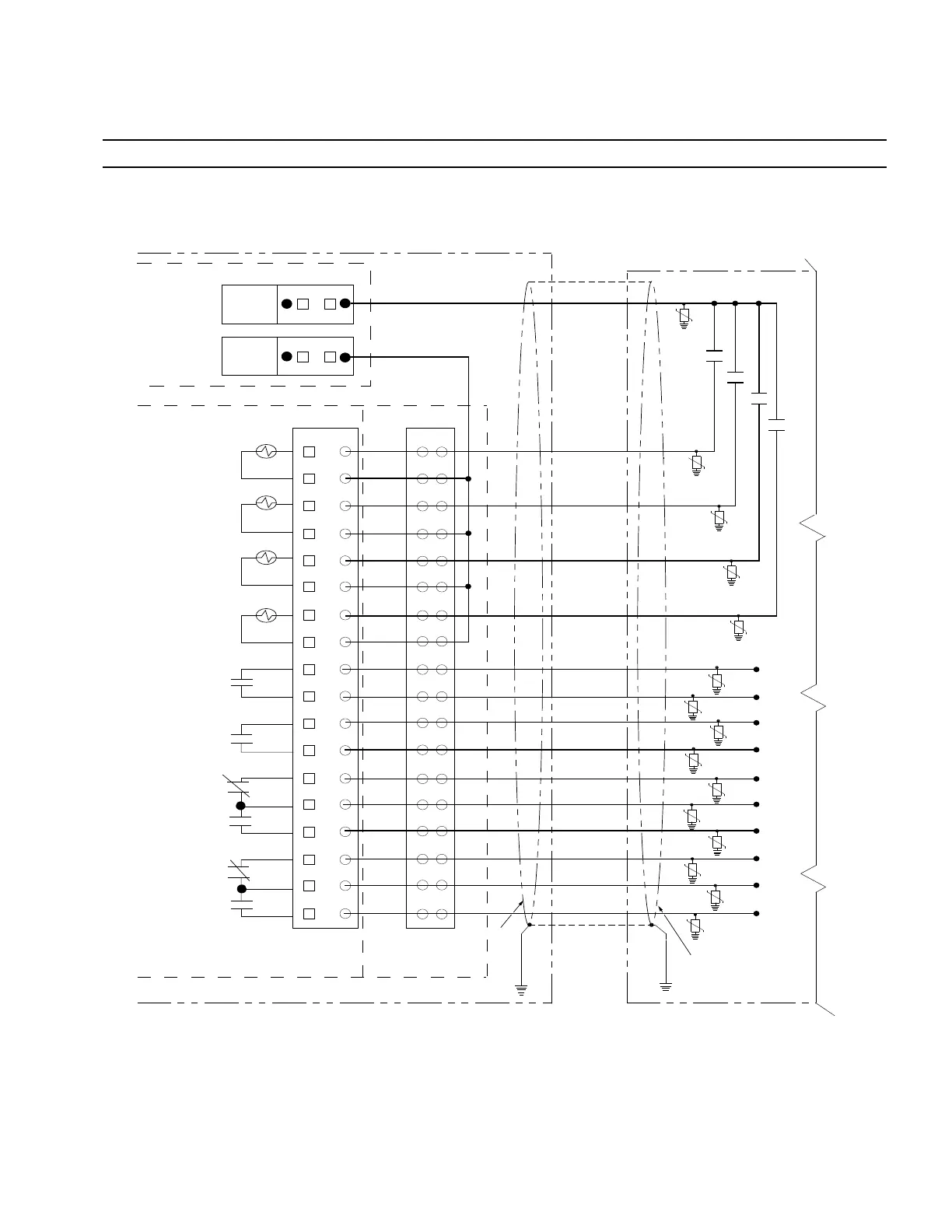
NOTICE
External leads must be shielded and the shield must be grounded at both ends. Terminate each lead with a 320VAC,
150 Joules metal oxide resistor (MOV), or equivalent, at the remote end. Attach MOVs between the leads and
ground. Failure to properly shield and protect leads c an result in equipment damage and/or unintentional operation.
FORM 4D CONTROL
Remote Terminal Unit (RTU)
Not All
Remote
Connections
Shown
Contact I/O
Module
J3
Recloser Trip and Lockout
Recloser Close
Ground Trip Block
Non-Reclose
Control Lockout Status
(Not Lockout)*
Recloser Open
(Recloser Not Open*)
Recloser Closed
(Recloser Not Closed)*
Control OK
(Control Not OK)*
18
17
16
15
14
13
12
11
10
9
8
7
6
5
4
3
2
1
TB1
WET
+
WET —
Control-Supplied
Whetting Voltage
24 VDC/100 mA
(Resettable-Fuse
Protected)
Shield
Shield
Back Panel
Terminal
Block
TB2
CO4-NO
CI1
CI1
CI2
CI2
CI3
CI3
CI4
CI4
CO1-NO
CO1-COM
CO2-NO
CO2-COM
CO3-NO
CO3-NC
CO3-COM
CO4-NC
CO4-COM
* Relay contacts shown for indicated status. This is also the de-energized state.
Figure 20. Customer connections to Contact I/O Module 1 with shielding and surge protection. (I/O functionality
shown is factory-default configuration for Module 1. The configuration is modifiable via Configurable Logic tool in
ProView NXG software)
25OPERATION INSTRUCTIONS MN280049EN September 2017
Form 4D Microprocessor-based pole-mount recloser control installation and operation instructions

 Loading...


