Catalog data MN650002EN
Effective February 2019
Deadbreak apparatus connectors
Step 9.
Install compression connector
ote:N Refer to the chart supplied with the crimp
connector for tool and die to be used.
•
Wire brush conductor (aluminum only).
•
Remove protective cap from compression connector.
•
Insert conductor completely into compression connector
and rotate connector to distribute inhibitor.
ote:N Connector must be fully seated on cable conductor.
•
Align flats of connector and apparatus bushing for
minimum conductor strain.
•
Make first crimp 1/2" (13 mm) below shoulder of
compression connector. (Refer to Figure 22).
•
Rotate each successive crimp 90° on compression
connector and allow 1/8" (3 mm) between crimps.
•
Wipe excess inhibitor from connector and adapter
surfaces.
Straight
Straight
Not straight
Not straight
bulge
Correct positioning
Cable
insulation
Cable
insulation
shield
Tape
marker
Incorrect positioning
Major OD
flared out
Figure 21. Cross sectional view of cable adapter
positioning.
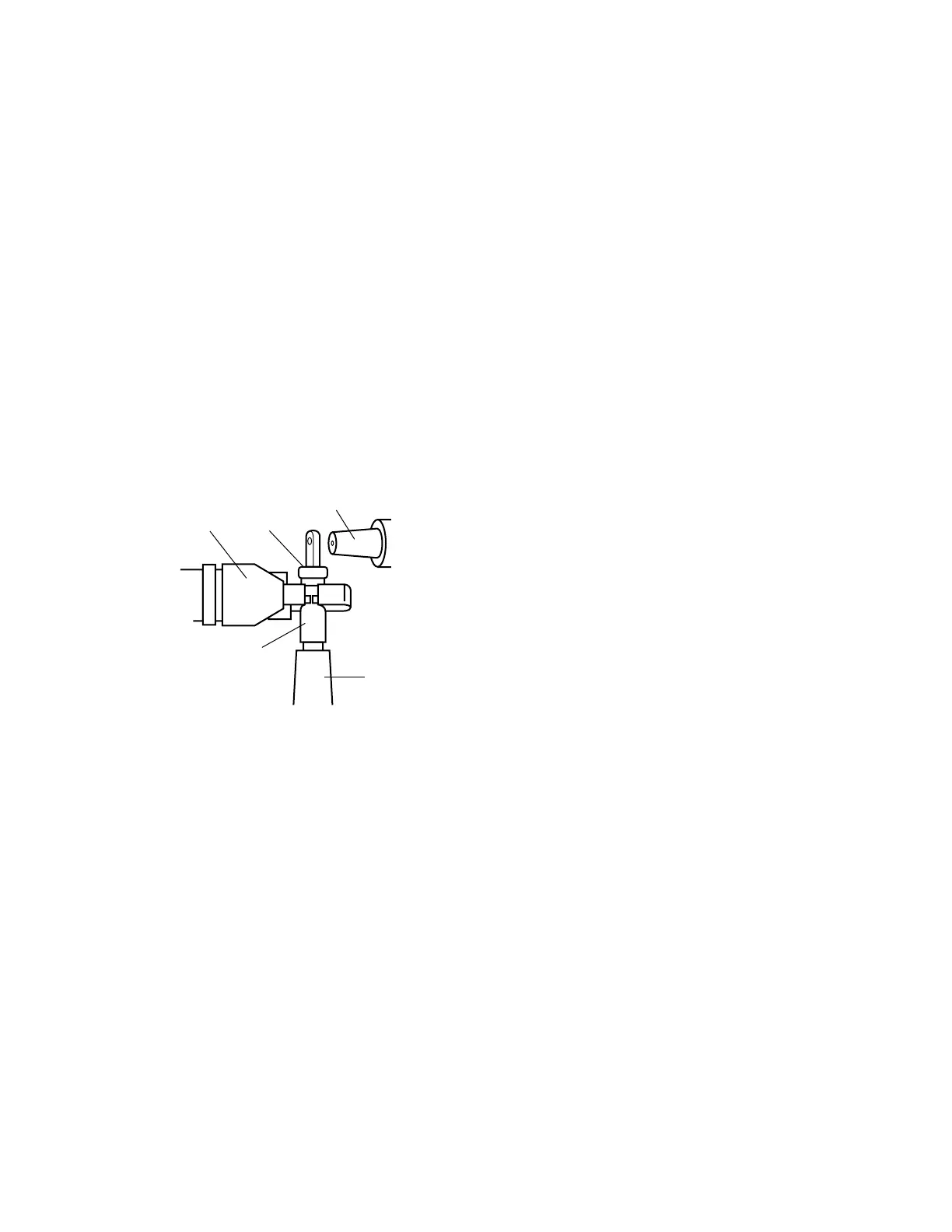
Figure 22. Line illustration of crimping area.
Bushing
ShoulderTool
Crimping
area
Cable
adapter
11
600 A 35 kV class BOL-T connector assembly installation instructions MN650002EN February 2019

 Loading...


