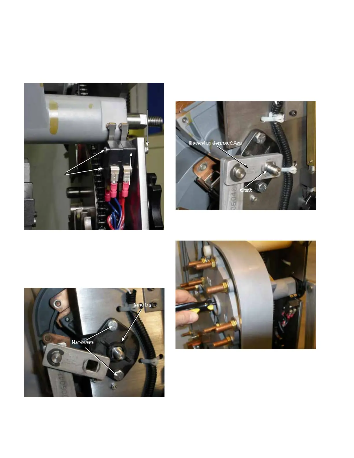
18. Place the mounting hardware onto the reversing logic
switches and fasten to the tap-changer front plate.
While holding a small screwdriver (or 5/32" Allen
wrench), tighten the nuts to a torque of 4–5 in-lbs (0.5–
0.6 Nm). See Figure 45.
19. If none is present on the threads, apply Loctite
®
243™
threadlocker to the two 1/4-28 bolts. Using the bolts
and a 7/16" wrench, fasten the reversing movable
bushing to the front of the tap-changer. Tighten the
bolts to a torque of 30–40 in-lbs (3.4–4.5 Nm). See
Figure 46.
20. Place the reversing segment arm onto the reversing
actuator shaft. Align the square portion of the shaft
with the square hole in the arm. If needed, place a
screwdriver through the movable contact tube and push
the shaft forward while seating the arm over the shaft.
It may be necessary to rotate the movable contact
assembly slightly to align the shaft and hole. See
Figures 47 and 48.
Figure 48. Positioning the reversing movable with the
bushing.
Figure 46. Reinstalling bushing.
Figure 47. Installing reversing segment arm.
Reversing Segment Arm
Shaft
Figure 45. Reinstalling logic switches.
Reversing
Logic
Switches
4-40
Hex
Nut
4-40x1.25
Screws
Hardware
Bushing
20
QD5 QUIK-DRIVE TAP-CHANGER INSTALLATION AND MAINTENANCE INSTRUCTIONS MN225012EN March 2016

 Loading...


