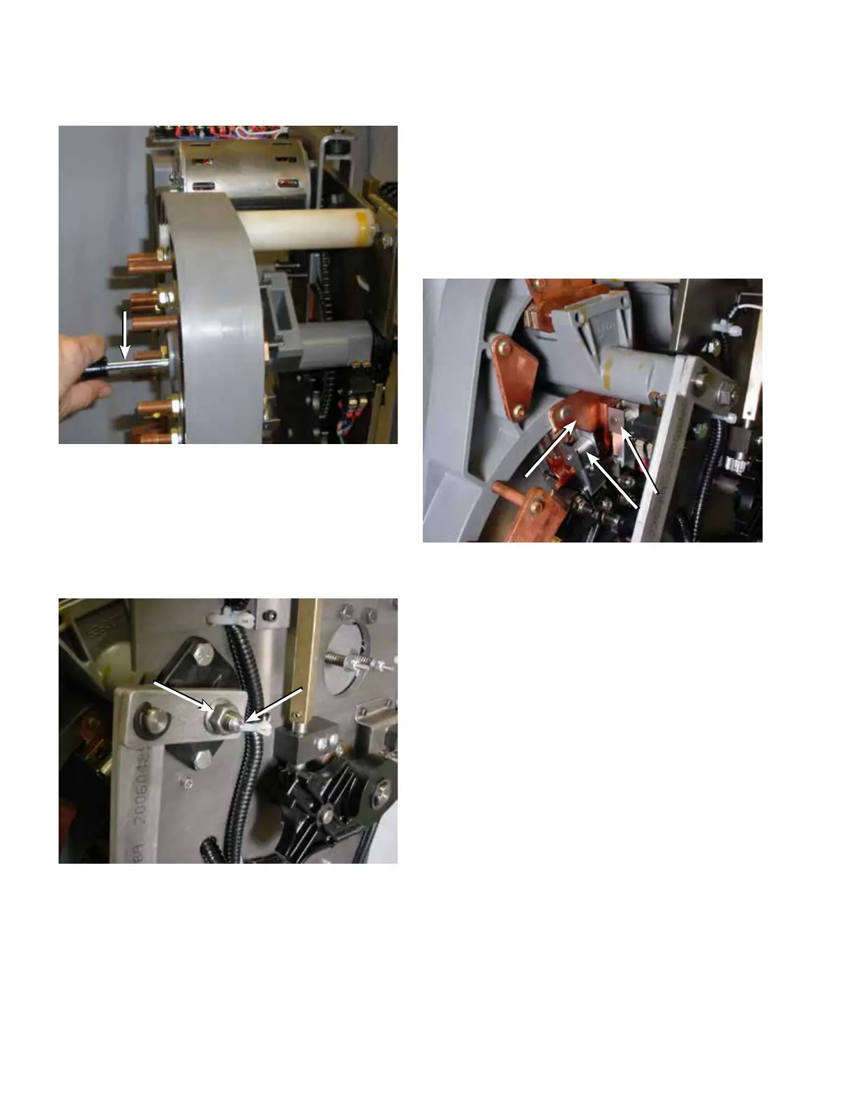
9. Place the self-locking nut onto the reversing segment
shaft. Using a 9/16" wrench, tighten to a torque of 180–
192 in-lbs (20.3–21.7 Nm) while holding the movable
contact assembly to prevent turning. See Figure 73.
10. Once the work has been completed, place the tap-
changer in the neutral position.
Placing tap-changer into neutral
1. Place a 3/8" socket and ratchet on the output shaft of
the motor; rotate the motor so that the contacts and
other components are aligned in the neutral position
2. Confirm that the regulator is in the neutral position.
A. Main movable contacts are located on the neutral
stationary contact, which is located at the 11 o’clock
position and under the reversing switch movable
contact assembly. See Figure 74.
Figure 73. Reversing segment fastening.
Reversing
Segment Shaft
3/8-16 Self-
Locking Nut
Figure 74. Neutral position for main movable contacts.
Figure 72. Pushing the reversing segment shaft forward.
Screwdriver or
Shaft Rod
Neutral
Stationary
Main
Movable
28
QD5 QUIK-DRIVE TAP-CHANGER INSTALLATION AND MAINTENANCE INSTRUCTIONS MN225012EN March 2016

 Loading...


