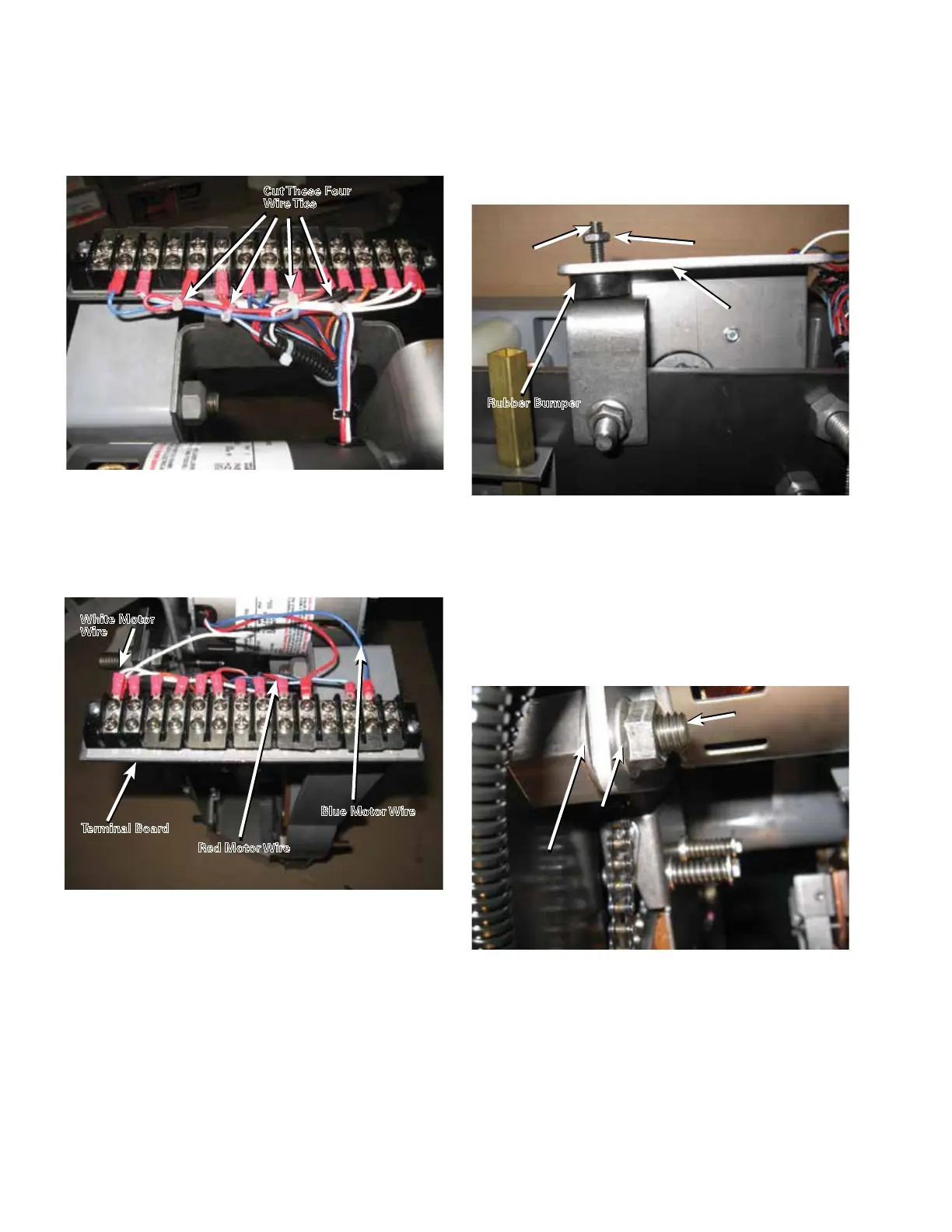
3. Use diagonal cutters to cut the four wire ties from the
motor wires. Refer to Figure 106.
4. Use a Phillips screwdriver to disconnect the white
motor wire located on terminal “G”, the red motor wire
located on terminal #5 and the blue motor wire located
on terminal #2. Refer to Figure 107.
5. Loosen the jam nut on the chain tension screw with
a 7/16" wrench. Loosen the chain tension screw with
a screwdriver until the rubber bumper is against the
motor mounting bracket. Refer to Figure 108.
6. If the tap-changer has a motor pivot stud design with
a lock nut as shown in Figure 109, remove the motor
pivot stud lock nut with a 9/16" socket on a ratchet. Pull
the motor off of the motor pivot stud; make sure the
Belleville washer stays on the motor pivot stud and
does not fall into the tank. Set the motor in the motor
relief area of the molded back panel. Refer to Figure
113 .
Figure 106. Removal of wire ties.
Cut These Four
Wire Ties
Figure 107. Disconnection of wires.
Figure 108. Loosening the chain tension.
White Motor
Wire
Terminal Board
Blue Motor Wire
Red Motor Wire
Motor Mounting
Bracket
Chain Tension
Screw
Jam Nut
Rubber Bumper
Figure 109. Motor pivot stud design.
Motor Pivot
Stud
Motor Pivot
Lock Nut
Belleville
Washer
40
QD5 QUIK-DRIVE TAP-CHANGER INSTALLATION AND MAINTENANCE INSTRUCTIONS MN225012EN March 2016

 Loading...


