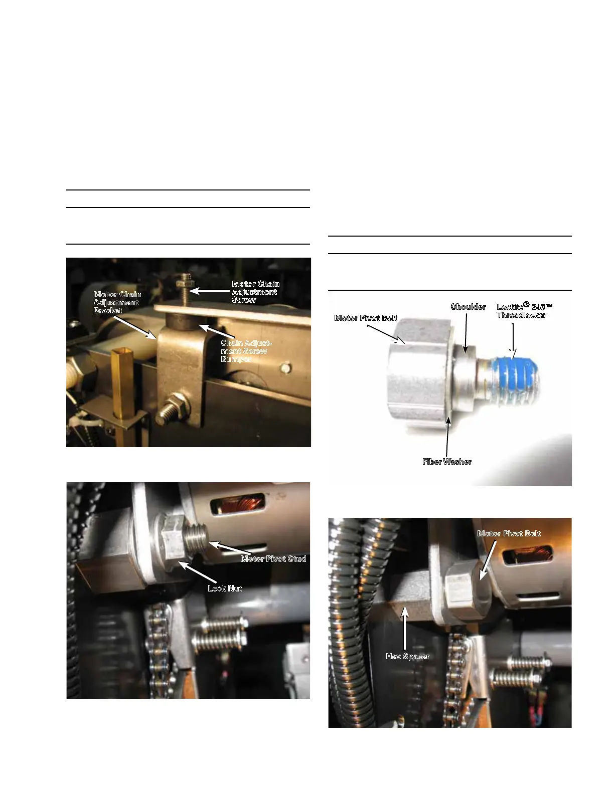
15. Apply Loctite® 243™ threadlocker on the threads of
the motor pivot bolt and verify the fiber washer is
still located on the motor pivot bolt shoulder. Refer to
Figure 120. Move the motor assembly into position
with the motor chain adjustment screw bumper located
on top of the adjustment bracket. Refer to Figure 118.
Align the hole in the motor mounting plate with the
hex spacer hole. Insert the motor pivot bolt through
the motor mounting plate and hand tighten into the
hex spacer. Refer to Figure 124. Make sure that the
shoulder on the bolt is completely inserted through the
hole in the motor mounting bracket. Using a torque
wrench with a 3/4" socket, tighten the motor pivot bolt
to 45–55 in-lbs (5.0–6.1 Nm).
14. Move the motor assembly into position with the motor
chain adjustment screw bumper located on top of the
adjustment bracket and the motor pivot stud inserted
through the mounting hole in the motor mounting
plate. Secure the motor mounting plate to the motor
pivot stud with the locknut removed in Step 6. Refer
to Figures 118 and 119. Using a torque wrench with a
9/16" socket, tighten the pivot motor stud locknut to
180–192 in-lbs (20.0–21.1 Nm). Proceed to Step 16.
Figure 121. Placement of motor pivot bolt.
Motor Pivot Bolt
Hex Spacer
Figure 118. Motor positioning.
Motor Chain
Adjustment
Bracket
Motor Chain
Adjustment
Screw
Chain Adjust-
ment Screw
Bumper
Figure 120. Motor pivot bolt.
Fiber Washer
Motor Pivot Bolt
Loctite
®
243™
Threadlocker
Shoulder
Figure 119. Motor pivot stud.
Motor Pivot Stud
Lock Nut
IMPORTANT
Make sure that the mounting hole in the motor mounting
bracket is fully seated on the shoulder of the mounting bolt.
If it is not fully seated, the chain may bind and fall off.
IMPORTANT
Make sure that the mounting hole in the motor mounting
bracket is fully seated on the shoulder of the mounting bolt.
If it is not fully seated, the chain may bind and fall off.
43
QD5 QUIK-DRIVE TAP-CHANGER INSTALLATION AND MAINTENANCE INSTRUCTIONS MN225012EN March 2016

 Loading...


