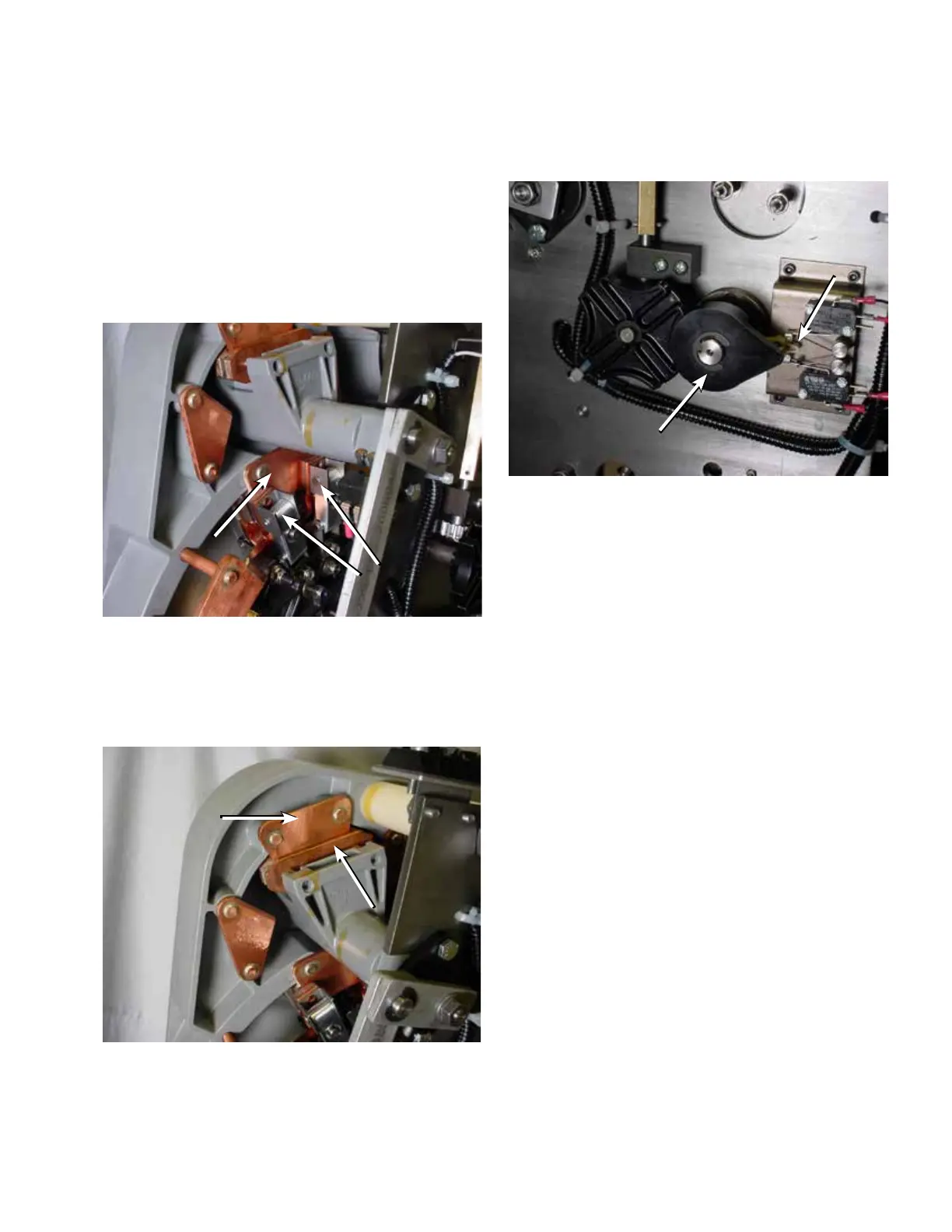
C. The pinion cam is pointing to the right over the
holding switch actuator. See Figure127.
Placing tap-changer into neutral
1. Place a 3/8" socket and ratchet on the output shaft of
the motor; rotate the motor so that the contacts and
other components are aligned in the neutral position
2. Confirm that the regulator is in the neutral position.
A. Main movable contacts are located on the neutral
stationary contact, which is located at the 11 o’clock
position and under the reversing switch movable
contact assembly. See Figure 125.
B. The reversing movable contact is located on the
reversing neutral stationary contact. See Figure126.
Figure 125. Neutral stationary contact.
Neutral
Stationary
Main
Movables
Figure 127. Neutral position for position indicator pinion
cam and holding switch.
Figure 126. Neutral position for reversing movable.
Reversing
Movable
Contact
Reversing
Neutral
Stationary
Pinion Cam
Holding Switch
Actuator
45
QD5 QUIK-DRIVE TAP-CHANGER INSTALLATION AND MAINTENANCE INSTRUCTIONS MN225012EN March 2016

 Loading...


