4. Using a 3/8” socket on a ratchet, rotate the shaft on the
back of the motor to move the movable contacts into
the space opened up when the number 1 stationary
contact was removed.
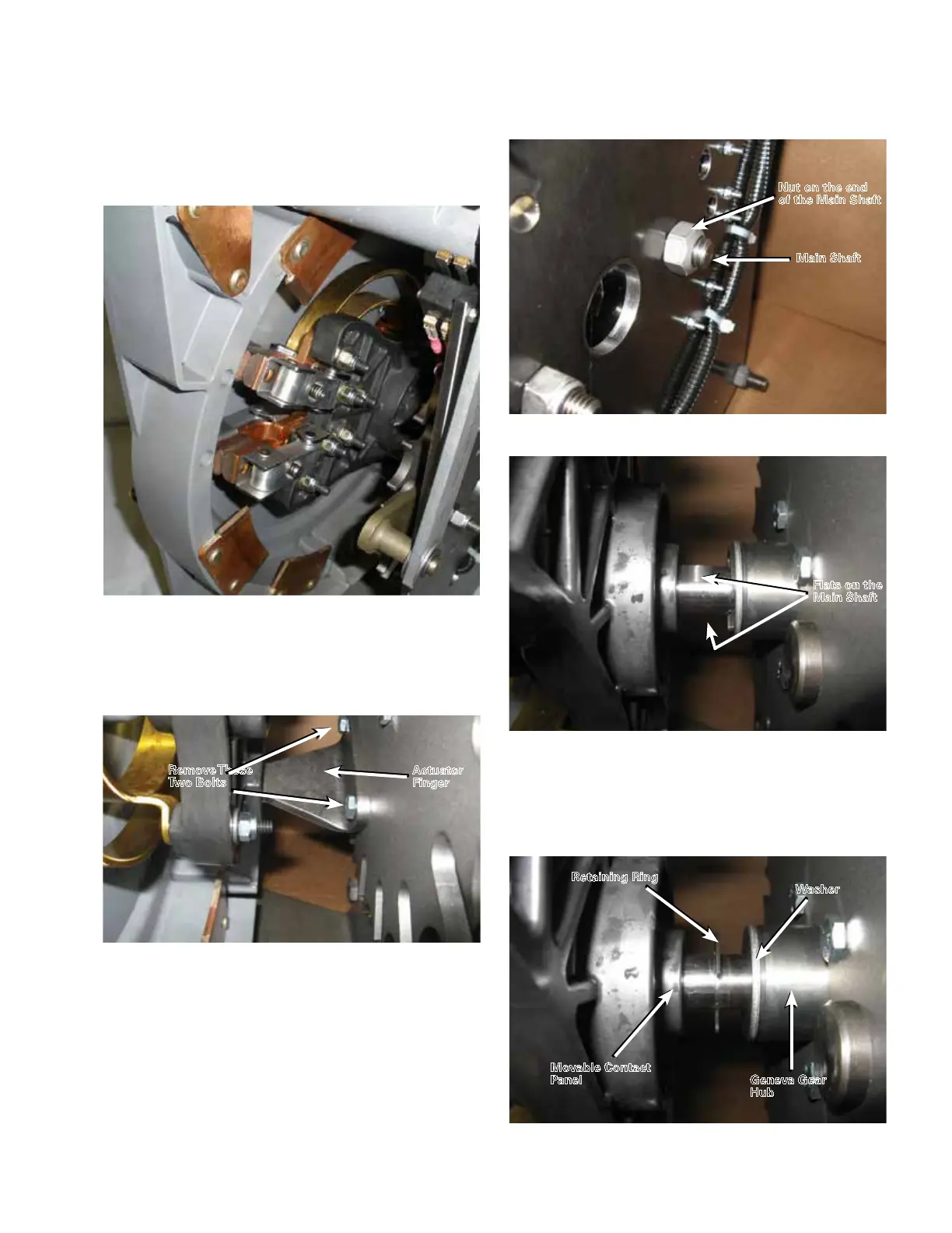
5. Remove the two bolts that mount the actuator finger
with a 7/16" socket wrench. Remove the actuator finger.
Refer to Figure 132.
6. Remove the nut on the end of the main shaft using
a 3/4" socket wrench. Use a 5/8" open end wrench
positioned on the flats of the main shaft to hold the
shaft in place during this procedure. Refer to Figures
133 and 134.
7. Push the main shaft from the threaded end partially
through the steel front plate of the tap-changer so
that the retaining ring on the main shaft is centered
between the movable contact panel and the washer/
Geneva gear hub. Refer to Figure 135.
Figure 134. Main shaft.
Flats on the
Main Shaft
Figure 133. Fastening nut for main shaft.
Nut on the end
of the Main Shaft
Main Shaft
Figure 135. Shaft positioning.
Washer
Geneva Gear
Hub
Retaining Ring
Movable Contact
Panel
Figure 132. Actuator finger.
Remove These
Two Bolts
Actuator
Finger
Figure 131. Main movable contacts in number 1 station-
ary position.
47

 Loading...


