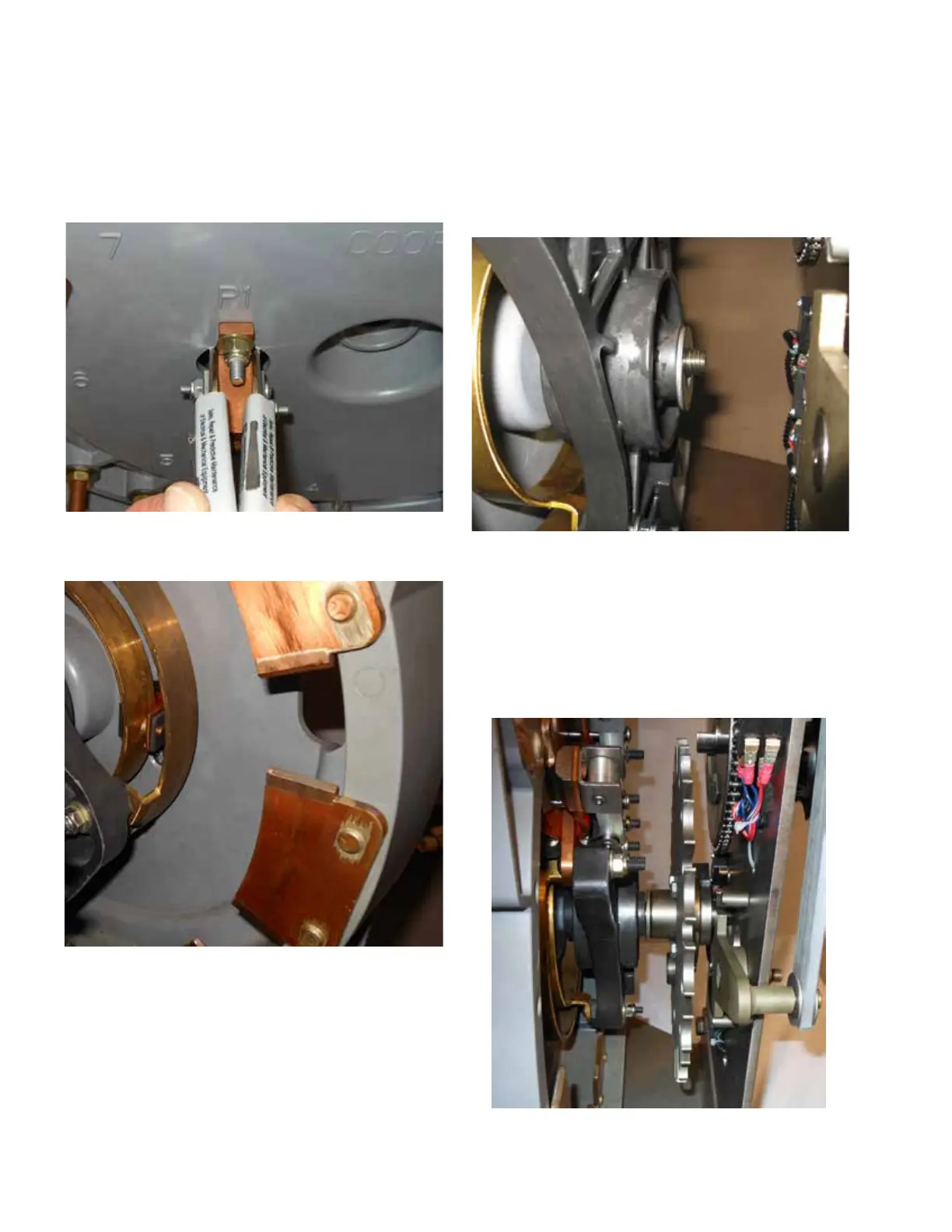
16. Squeeze the handles of the small screwdrivers together
to spread apart the button contacts. Push the aligned
ring contact in between the button contact so the
buttons are fully engaged with the contact ring. Refer
to Figures 144 and 145.
1 7. Insert the threaded end of the main shaft through the
back of the molded panel, then through the movable
contact panel until the threads of the shaft are just
protruding out of the movable contact panel. Slide the
washer onto the main shaft and position it against the
movable contact panel. Refer to Figure 146.
18. Line up the main shaft with the hole in the Geneva
gear. Push the shaft through Geneva gear until the
threaded end of the shaft reaches the steel front plate.
Lift on Geneva gear to assist in lining up the shaft
with the hole in the front plate. Insert the shaft tip
just slightly into the hole. The Geneva gear should be
rotating freely on the shaft. See Figures 147 and 148.
Figure 145. Ring and P1 contacts.
Figure 144. Installing ring into P1 contact.
Figure 147. Geneva gear rotating freely on main shaft.
Figure 146. Installing main shaft.
50
QD5 QUIK-DRIVE TAP-CHANGER INSTALLATION AND MAINTENANCE INSTRUCTIONS MN225012EN March 2016

 Loading...


