Effective May 2010 2C15999H02
05/10 AWA1230-2445
Auxiliary switch kit in
IZM low voltage circuit breakers
WARNING
(1) ONLY QUALIFIED ELECTRICAL PERSONNEL SHOULD
BE PERMITTED TO WORK ON THE EQUIPMENT.
(2) ALWAYS DE-ENERGIZE PRIMARY AND
SECONDARY CIRCUITS IF A CIRCUIT BREAKER
CANNOT BE REMOVED TO A SAFE WORK LOCATION.
(3) DRAWOUT CIRCUIT BREAKERS SHOULD BE
LEVERED (RACKED) OUT TO THE DISCONNECT
POSITION.
(4) ALL CIRCUIT BREAKERS SHOULD BE SWITCHED
TO THE OFF POSITION AND MECHANISM SPRINGS
DISCHARGED.
FAILURE TO FOLLOW THESE STEPS FOR ALL
PROCEDURES DESCRIBED IN THIS INSTRUCTION
LEAFLET COULD RESULT IN DEATH, BODILY INJURY,
OR PROPERTY DAMAGE.
WARNING
THE INSTRUCTIONS CONTAINED IN THIS AWA AND ON
PRODUCT LABELS HAVE TO BE FOLLOWED. OBSERVE
THE FIVE SAFETY RULES:
– DISCONNECTING
– ENSURE THAT DEVICES CANNOT BE
ACCIDENTALLY RESTARTED
– VERIFY ISOLATION FROM THE SUPPLY
– EARTHING AND SHORT-CIRCUITING
– COVERING OR PROVIDING BARRIERS TO
ADJACENT LIVE PARTS
DISCONNECT THE EQUIPMENT FROM THE SUPPLY.
USE ONLY AUTHORIZED SPARE PARTS IN THE REPAIR
OF THE EQUIPMENT. THE SPECIFIED MAINTENANCE
INTERVALS AS WELL AS THE INSTRUCTIONS FOR
REPAIR AND EXCHANGE MUST BE STRICTLY ADHERED
TO PREVENT INJURY TO PERSONNEL AND DAMAGE TO
THE SWITCHBOARD.
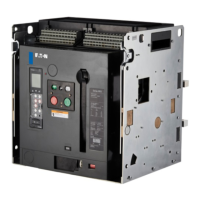
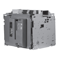
Section 1: General information
An auxiliary switch is an optional device providing
remote electrical indication if the circuit breaker is
open or closed. Up to three auxiliary switches can
be mounted in the circuit breaker. Each switch has
two normally open (“A”) and two normally closed
(“B”) contacts for a total of 12 available contacts.
Section 2: Installation of the
auxiliary switch
To install the auxiliary switch, proceed with the
following five steps:
Step 1: Remove the front cover by unscrewing
the hex head captive bolts (four for three-pole,
six for four-pole) that join the cover to the breaker
housing using a 10 mm 1/4-inch drive socket.
Then hold the charge handle down approximately
45 degrees to pull off the cover.
Step 2: Place the appropriate label on the
front cover nameplate space located under
“Accessories.”
Figure 1. Steps 1 and 2
Label
Bolt