Auxiliary switch kit in
IZM low voltage circuit breakers
Eaton Industries GmbH
Electrical Sector
©2010 by Eaton Industries GmbH
Änderungen vorbehalten
Subject to alterations
05/10 AWA1230-2445 / Z8696
Moon/Doku/Heng
Printed in USA (05/10)
05/10 AWA1230-2445
Effective May 2010
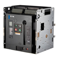
Step 3: Slide the lock on the switch to the unlocked (up) position.
Install the hook feet down through openings as shown. Then slide
the auxiliary switch forward so the feet engage the mounting plate.
Slide the lock down into the locked position.
Figure 2. Step 3
ote:N The number of auxiliary switches and shunt trips cannot exceed four.
Forward
Auxiliary Switch
Second Switch
Here
Mounting
Plate
Third Switch Here
First
Switch
Here
Hook
Feet
Lock
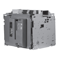
Step 4: Wire auxiliary switches per Table 1 and wire markings.
Figure 3. Step 4
ote:N Securely tie wires away from moving parts.
Table 1. Auxiliary Switch Secondary Wiring
Auxiliary Switch
IZM97/IZM32/IZM99/IZM63
Frame Breaker
IZM20/IZM93
Frame Breaker
#1 Contacts B20–B27 Contacts B20–B27
#2 Contacts A27–A30, B16–B19 Contacts A19–A26
#3 Contacts A19–A26 —
Step 5: Reinstall front cover removed in Step 1.
Secondary Block “A”
Secondary Block “B”

 Loading...