Do you have a question about the Eaton BRMIKCSR and is the answer not in the manual?
List of tools and components required but not supplied with the kit.
Inventory of all parts included in the mechanical interlock kit.
Ensure electrical power to the loadcenter is disconnected before starting installation.
Detach the enclosure's trim or door by removing all screws.
Find the hold-down retainer on the interior backpan near the main bus.
Snap the generator hold-down retainer into the interior backpan.
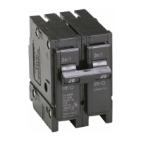
Mount the generator breaker onto the main bus.
Thread and tighten the provided screw to secure the generator breaker.
Position the trim/door face down on a firm surface for drilling.
Drill four pilot holes in the trim/door at the designated points.
Attach the mechanical interlock assembly to the trim/door using screws.
Place the provided labels in their designated locations.
Reinstall the trim/door onto the enclosure using the original screws.
Test to ensure the interlock prevents simultaneous ON positions for both breakers.
Position the non-drilled trim/door face down on a firm surface for drilling.
Attach the interlock assembly to the non-drilled trim/door using screws.
Drill four pilot holes in the non-drilled trim/door using a 5/32-inch drill bit.
Detach the interlock assembly from the trim/door by removing screws.
Drill the four mounting holes using a 3/16-inch drill bit on pilot holes.
Smooth the newly drilled mounting holes to remove burrs.
Re-attach the interlock assembly to the non-drilled trim/door using screws.
Place the label on the non-drilled trim/door as shown in Figure 5.
Reinstall the non-drilled trim/door onto the enclosure using original screws.
Confirm the interlock prevents simultaneous ON positions for both breakers.
| Voltage Rating | 120/240V AC |
|---|---|
| Interrupting Capacity | 10 kA |
| Series | BR |
| Breaking Capacity | 10 kA |
| Mounting | Plug-in |
| Amperage Rating | 100A |
| Number of Poles | 1 |
| Current Rating | 100A |
| Poles | 1 |