EasyManua.ls Logo

Eaton K1650 - User Manual

Eaton K1650
24 pages
Print Icon
To Next Page IconTo Next Page
Loading...
K1650 & K6050
MTL alternator purge gas analysers
January 2017
INM MTL 130-0126 Rev 13
Instruction manual
MTL gas analysers & systems

Questions and Answers

  • A
    Amber SilvaAug 20, 2025
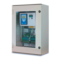
    What to do if the Power LED is not lit on my Eaton Industrial Electrical?
    • S
      srussellAug 20, 2025
      If the Power LED is not lit on your Eaton Industrial Electrical, you should first check the polarity and integrity of the trunk cable connections to the enclosure. Also, verify that the d.c. supply powering the incoming trunk is operating correctly.
  • J
    jamiekimAug 22, 2025
    What to do if the power LED is not lit on my Eaton Control Unit?
    • G
      Gloria PollardAug 22, 2025
      If the power LED on your Eaton Control Unit isn't lit, verify the polarity and integrity of the trunk cable connections to the enclosure. Also, check that the d.c. supply powering the incoming trunk is operating correctly.
  • E
    Erika JonesAug 25, 2025
    What to do if alarms on my Eaton Security System remain on and cannot be reset?
    • H
      heidifrazierAug 25, 2025
      If alarms are set to operate from normally closed contacts and the signal supply fuse blows, all alarms will operate as though an alarm has occurred. To resolve this, check the signal supply fuse F1 (rated at 125mA), located in the top right-hand corner of the unit when viewed from the rear, to see if it has blown. Also, ensure that the inputs have been correctly set to operate from either a normally open (N.O.) or normally closed (N.C.) configuration and haven't been accidentally inverted.
  • M
    Matthew RamseyAug 27, 2025
    How to fix the audible alarms not sounding on my Eaton Security System?
    • S
      santosjoshuaAug 27, 2025
      Each channel can be selected to operate either of the two integral horns / horn relays as required. Internal horns and horn relays are enabled by placing the following switches to the ON position on the SPR Card: HNA – SW5 - Position 5, HNB – SW5 - Position 6. Each pair of channels can be set to activate either of the audibles using the following switches located on each alarm module: Channel 1 & 2 HNA – SW4 Position 7 set to ON, HNB – SW4 Position 8 set to ON; Channel 3 & 4 HNA – SW6 Position 7 set to ON, HNB – SW6 Position 8 set to ON.
  • J
    Joseph GrayAug 28, 2025
    What to do if signal inputs that alarm and quickly return to normal are not being picked up by the Eaton Security System annunciator?
    • M
      Matthew WhiteAug 28, 2025
      Check that the response time has been set to suit the application.
  • J
    Jacob LarsonAug 30, 2025
    Why individual repeat relays do not act as slaves of the signal input on my Eaton Security System?
    • J
      johnsonloriAug 30, 2025
      The operation of the repeat relays is selectable by the user to either follow the signal contact or to remain in the alarm state until the input has returned to normal and the operator has cleared the alarm.
  • H
    hhamiltonAug 31, 2025
    How to troubleshoot a non-lit green LED for supply 1 and active power failure alarm on my Eaton Security System?
    • M
      Miguel BrownAug 31, 2025
      Measure the voltage on the power input terminals marked supply 1 located on the rear of the unit and verify that the level matches the requirement and is connected in the polarity indicated.
  • E
    Ellen GonzalesSep 2, 2025
    How to troubleshoot a non-lit green LED for supply 2 and active power failure alarm on my Eaton Security System?
    • D
      Dustin RasmussenSep 3, 2025
      Measure the voltage on the power input terminals marked supply 2 located on the rear of the unit and verify that the level matches the requirement and is connected in the polarity indicated.
  • P
    Patricia TylerSep 4, 2025
    What to do if no alarm occurs on the annunciator when the signal input contact closes or opens on my Eaton Security System?
    • B
      Brandon FrostSep 4, 2025
      Check that the signal supply fuse F1 rated @ 125mA, located in the top right hand corner when viewed from the rear of the unit, is in working order and check that the corresponding signal supply voltage is present on the customer terminals on the rear of the unit which can be measured between terminals OVC and any of the terminals marked C (Common) located at the top of each row of signal input terminals.
  • V
    Victoria BartonSep 6, 2025
    How to solve the Individual channel Repeat Relay contact is Normally Closed in the non alarm state but should be Normally Open on my Eaton Security System?
    • B
      Brandon MurphySep 6, 2025
      Each pair of repeat relays can be set to normally energised or normally de-energised using switches located on the Alarm Card and the contact state can also be selected as normally open or closed.

Eaton K1650 Specifications

General IconGeneral
BrandEaton
ModelK1650
CategoryLighting Equipment
LanguageEnglish

Related product manuals