18
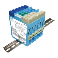
6 UNIT DESCRIPTIONS, SETTING-UP AND CONNECTIONS
This section describes the function (briefly), the setting-up procedure and the wiring connections
for each MTL5500 unit. For a fuller functional description and a detailed technical specification,
refer to the individual datasheets, which can be found on our website at http://www.mtl-inst.com
or in the current MTL IS catalogue.
If a fault is suspected, first check that the power LED is lit (not applicable to loop-powered
devices). If necessary, check that all signal and power plugs are properly inserted, that no wires
are loose and that the unit is mounted correctly. If operation is still suspect, the unit should be
replaced with a serviceable unit.
There are no replaceable parts inside MTL5500 units, so any that appear to be inoperative should
be returned to the manufacturer/supplier for repair or replacement.
WARNING
When disconnecting units for maintenance purposes, take care to
segregate hazardous and safe-area cables.
• Short circuit hazardous-area cable cores to an IS earth or insulate and
secure the ends.
• Insulate and secure safe-area cables. If testing a unit ‘in situ’ note that
the test equipment used MUST be intrinsically safe.
The rest of this section is divided into sub-sections based upon the type of module, as follows.
6.1 Digital Input modules
MTL5501-SR, MTL5510, MTL5510B, MTL5511, MTL5513, MTL5514, MTL5514-T,
MTL5514D, MTL5516C, MTL5517
6.2 Digital Output modules
MTL5521, MTL5521 -T, MTL5522, MTL5523, MTL5523V, MTL5523VL, MTL5524,
MTL5525, MTL5526
6-3 Pulse and Vibration modules
MTL5531, MTL5532, MTL5533
6.4 Analogue Input modules
MTL5541, MTL5541A, MTL5541AS, MTL5541S, MTL5541S-T, MTL5544, MTL5544A,
MTL5544AS, MTL5544D, MTL5544S
6.5 Analogue Output modules
MTL5546, MTL5546Y, MTL5546Y-T, MTL5549, MTL5549Y
6.5 Fire and Smoke interface modules
MTL5561
6.7 Temperature Input modules
MTL5573, MTL5575, MTL5576-RTD, MTL5576-THC, MTL5581, MTL5582, MTL5582B
6.8 General modules
MTL5599, MTL5991
6.9 PCS45/PCL45USB configurator for MTL temperature converters
Note: Any LED indicator provided on the modules will display in the following colours:
LED label LED colour
PWR (power) Green
STS (status) Yellow
LFD (line fault) Red
FLT (fault) Red
OPx (o/p status) Yellow
 Loading...