EasyManuals Logo

Eaton MTL5514D User Manual

Eaton MTL5514D
88 pages
To Next Page IconTo Next Page
To Previous Page IconTo Previous Page
Page #37 background imageLoading...
Page #37 background image
INM 5500 Rev 11
29
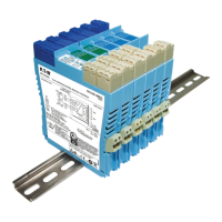
6.1.9 MTL5517 - Switch/Proximity detector interface
Two channel, with line-fault detection and phase reversal
The MTL5517 enables two safe-area loads to be controlled, through a relay, by switches or
proximity detectors located in a hazardous-area. When selected, the line-fault detect (LFD) is
signalled through a separate relay and indicated on the top of the module. Line-Fault Detect
and Phase Reversal for the channel are selected by DIL switches on the side of the module
and output is provided by the relay contacts.
See page 19 for LFD and PR switch details. Channel 1 & 2 switch settings apply.
For switch sensor inputs, with LFD selected, make sure resistors (22k
and 680
) are fitted.
Note: For reliable, long-term operation the load on the output switching relays should be not less
than 50mW, e.g. 10mA at 5V DC.
Vs–
Vs+
20 to 35V dc
LFD
+
+
Switch-type sensors
require resistors
if LFD is selected
Ch 2
Ch 1
LFD
22k
680
22k
680
6
5
4
3
2
1
7
8
9
10
11
12
13
14
LFD
Hazardous area
Safe
are
a








Terminal Function
1 Input –ve (Ch 1)
2 Input +ve (Ch 1)
4 Input –ve (Ch 2)
5 Input +ve (Ch 2)
7 Line-fault detection
8 Output (Ch 2)
9 Output (Ch 2)
10 Line-fault detection
11 Output (Ch 1)
12 Output (Ch 1)
13 Supplyve
14 Supply +ve
Figure 6.9:
Top label
for MTL5517

Table of Contents

Questions and Answers:

Question and Answer IconNeed help?

Do you have a question about the Eaton MTL5514D and is the answer not in the manual?

Eaton MTL5514D Specifications

General IconGeneral
BrandEaton
ModelMTL5514D
CategoryIndustrial Equipment
LanguageEnglish

Related product manuals