11
Instructional Booklet IB02102006E
Effective May 2011
Type MVS (previously WLI)
metal-enclosed switchgear—
4.76 kV, 15.0 kV, 27.0 kV, and 38.0 kV
EATON CORPORATION www.eaton.com
Field taping of electrical connections
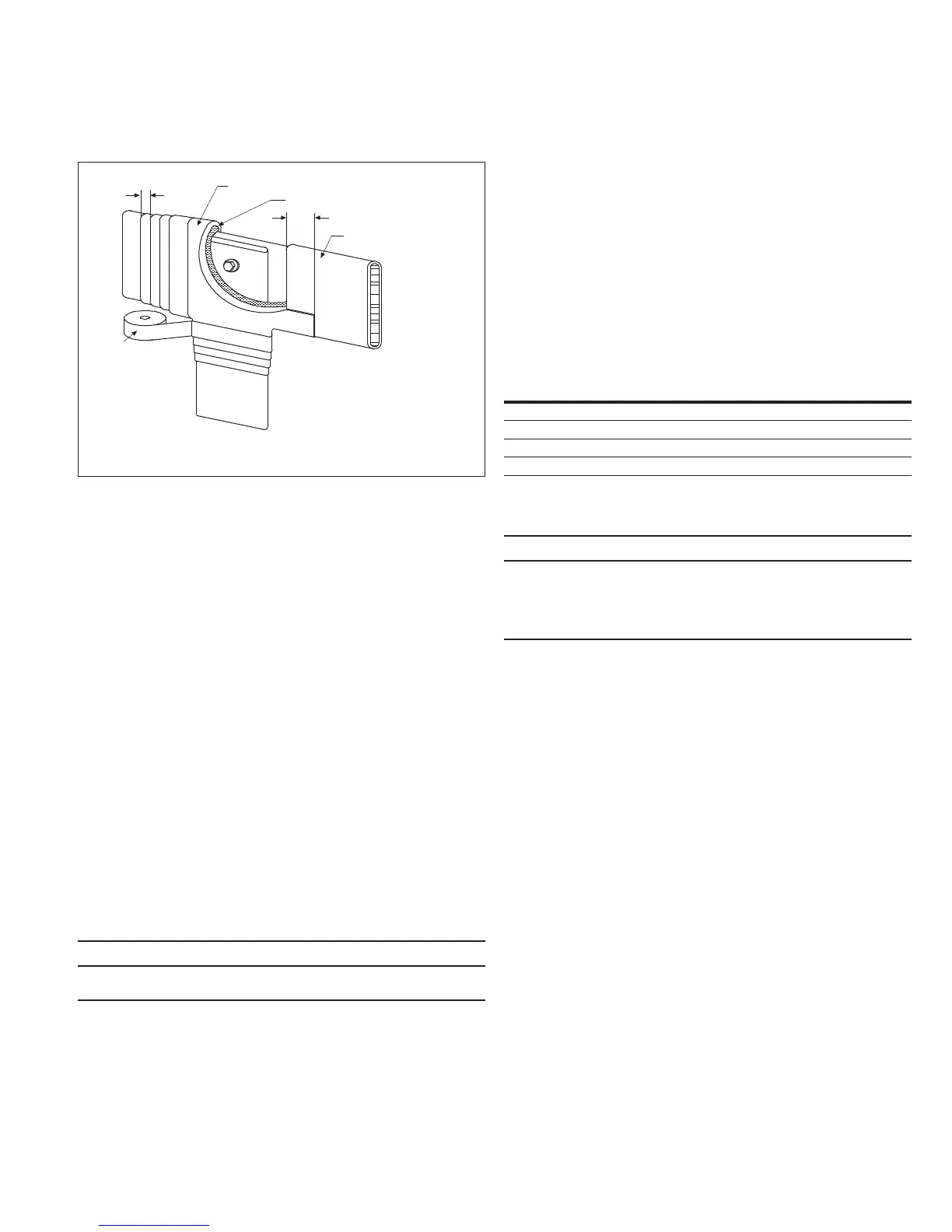
During the following procedures, please refer to Figure 16.
Figure 16. Field Taping of Electrical Connections
Definitions and Eaton approved materials for
field insulation
Filler: Nashua No. 102 Duct SealerT or 3M Co. ScotchfilT or NeerT
Duct Seal.
Insulating tape and pad: Either 3M Co. Scotch 23T or
Scotch 130CT.
Insulating boot: Molded plastic cover that is put over a joint and
fastened in place with wire ties.
Joint: An area to be insulated. This consists of the bare conductor
and 1.50 inches (38.1 mm) of any pre-insulation next to the
bare conductor.
Layer: Insulating tape, 1.00-inch (25.4 mm) wide, wrapped from one
end of the joint to the other (or to a pad) so that each succeeding
turn laps the previous turn by the amount specified in the
taping chart.
Overlap: A specified distance measured along the pre-insulation
starting from the point where the pre-insulation ends and where
the exposed conductor begins.
Pad: Any insulating tape applied that is wider than 1.00 inch
(25.4 mm). Includes a band of tape consisting of one or more
turns wrapped directly on top of each other.
Pre-insulation: Any insulation covering (sleeving materials such
as NORYLT, RaychemT, ScotchititeT, and fluidized epoxy coating)
adjacent to an exposed conductor prior to insulating.
WARNING
THE USE OF SOLVENTS, OILS, JOINT COMPOUNDS, OR GREASE ON OR
NEAR NORyL INSULATION WILL DESTROy IT.
1-1/2" (Minimum Lap)
Filler
Pre-Insulation
Typical Insulating Tape and Pad
Insulating
Tape
Pad
Lap
Responsibility of installer
•
For incoming or outgoing terminations, these approved materials
are not supplied by Eaton and must be obtained and installed by
others as identified in the definitions on this page.
•
For connections involving shipping splits within an MVS switchgear
assembly, or connecting to a transformer, or to an AMPGARD
MCC, or to an MVA switchgear assembly, or to a medium voltage
bus run, insulating materials will be supplied if necessary by Eaton
It is the responsibility of the installer to insulate the connections in
accordance with these instructions
•
For a switchgear assembly that does not have continuous insulating
sleeving on the phase bus conductors and where the dimensions
in Table 1 are not met at field assembled connections,
insulation of these connections must be made
Table 1. Minimum Clearance Chart
kV Rating of the
MVS Switchgear
Phase-to-Phase
a
Inches (mm)
Phase-to-Ground
Inches (mm)
4.76 3.50 (88.9) 3.50 (88.9)
15 6.00 (152.4) 6.00 (152.4)
27 8.00 (203.2) 8.00 (203.2)
38 10.50 (266.7) 10.50 (266.7)
a
If the phase-to-phase clearances above for a given rating do not exist, then it is only necessary to
insulate the center phase.
CAUTION
FAILURE TO INSTALL FIELD INSULATION WHERE NECESSARy IN
ACCORDANCE WITH THESE INSTRUCTIONS WILL COMPROMISE THE
ELECTRICAL RATINGS OF THE SWITCHGEAR ASSEMBLy.
INSTALL FIELD INSULATION TO MAINTAIN THE ELECTRICAL RATINGS.