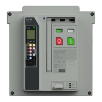
Do you have a question about the Eaton Power Xpert Release PXR 20 and is the answer not in the manual?
| Brand | Eaton |
|---|---|
| Model | Power Xpert Release PXR 20 |
| Category | Power distribution unit |
| Language | English |
Covers viewing and editing protection settings using PXPM software.
Describes changing passwords, date/time, and resetting trip unit values.
Explains testing capabilities via secondary injection system.
Details how to find breaker and trip unit identification information.
Explains viewing sensed information like currents, voltages, and power.
Describes viewing logged events and their categorization.
Covers creating PDF reports with breaker information and operating conditions.
Discusses software language, version, and contact info.
Mentions requesting value-added feature licenses for PXPM.
Overview of PXR trip unit features, flexibility, and applications.
Lists catalog numbers and styles of PXR trip units covered by the manual.
Details core protection functions and settings for PXR 20/25.
Describes additional protection features available for the PXR 25.
Explains real-time metering capabilities of PXR 20/25.
Describes the function and meaning of the STATUS indicator on the trip unit.
Details the trip unit's display screen and buttons for navigation and configuration.
Explains the LED indicators that show the cause of a trip event.
Explains how to configure PXR 20 settings using rotary switches.
Details configuring PXR 25 settings via the display and menu system.
Describes the switch for enabling Arc Flash Reduction Maintenance System (ARMS).
Explains the function of the RESET button on the trip unit.
Discusses the clear plastic cover for security and tamper resistance.
Details the USB port for configuration and monitoring using PXPM.
Information about the battery that supports the RTC and CoT indicators.
Indicates where to find the breaker's continuous current rating label.
Explains the trip unit's real-time clock for event timestamping.
Specifies operating and storage temperature ranges for the trip unit.
Describes the three main components of the PXR system.
Refers to the EULA document governing the use of PXR trip units.
Details password levels and security measures for settings access.
Explains settings for overload protection, including pickup and time delays.
Describes the LTM function for protecting against repeated overload conditions.
Covers settings for short delay pickup and time, including I2t response.
Explains the instantaneous protection setting and its indicator.
Discusses a factory-set function for tripping above withstand rating.
Details ground fault detection methods and settings.
Explains the default residual sensing method for ground fault protection.
Describes alternative sensing methods for ground faults.
Explains ground fault thermal memory for intermittent arcs.
Discusses ZSI for ground fault protection.
Details the pre-alarm feature for ground fault currents.
Introduces additional protection features for PXR 25.
Monitors line-to-line voltages against pickup and delay settings.
Monitors line-to-line voltages below pickup and delay settings.
Detects voltage differences between line-to-line phases.
Detects current differences between phase currents.
Protects against complete loss of one or two phases.
Monitors and acts on reverse real power flow.
Explains the Arc Flash Reduction Maintenance System (ARMS) function.
Details how to activate and indicate when maintenance mode is active.
Explains ZSI for fast tripping and coordination with other breakers.
Describes the MCR function to prevent closing on a faulted circuit.
Discusses adding external neutral sensors for 3-pole breakers.
Explains how relays can be configured for various trip unit conditions.
Details the integrated Modbus RTU communication protocol.
Covers CAMs for Ethernet or Profibus network integration.
Explains the need for auxiliary power for full functionality.
Provides details on secondary wiring terminals and their use.
Discusses integrating PXR with supervisory systems via Modbus or relays.
Explains automatic recording of events, alarms, and trips, including waveforms.
Details the algorithm monitoring circuit breaker health and providing insights.
Describes built-in test modes without a separate kit.
Explains performing functional tests using secondary injection.
Covers performance testing of ground fault protection systems.
Discusses considerations for testing PXR within switchgear.
Provides a matrix for diagnosing and resolving common trip unit issues.
Step-by-step guide for replacing the PXR trip unit in the field.
Instructions for replacing the trip unit's battery.
Explains how to modify the breaker's rated current using PXPM software.
Covers setting Modbus network parameters like address and baud rate.
Details Modbus connection parameters configurable from the LCD or PXPM.
Lists Modbus exception codes and their meanings.
Details registers for configuring Modbus data response.
Mentions Modbus diagnostics for port communication monitoring.
Describes input status bits for breaker status and validity.
Explains real-time data registers for current, voltage, power, and other parameters.
Details registers for sending commands to the trip unit for remote operation.
Explains how to access and synchronize the trip unit's date and time.
Describes registers for accessing historical event data.