6
Instructional Booklet IB02102006E
Effective May 2011
Type MVS (previously WLI)
metal-enclosed switchgear—
4.76 kV, 15.0 kV, 27.0 kV, and 38.0 kV
EATON CORPORATION www.eaton.com
Connection to type MVS switchgear to a transformer
Physical connection
Indoor assemblies, dry-type, cast coil type, or liquid- filled
type transformers
Holes are predrilled in the side of the MVS structure to match the
holes provided in the transformer.
Outdoor throat connection, liquid-filled transformers
Refer to Figure 5 while completing the following procedure.
Step 1: Remove the sealing ring flange from the MVS switchgear
throat and set it aside.
Step 2: The switch and the transformer should be brought together
to provide spacing of approximately 0.50 inches (12.7 mm) between
the throat flanges.
Step 3: Apply the double-faced adhesive tape supplied with the
MVS switchgear to the outside surfaces of both flanges.
Step 4: Press the felt supplied with the MVS switchgear into place
on the adhesive tape. The felt is to seal against the entrance of dust
and to prevent transmission of the vibration produced by transformer
resonance to the MVS switchgear.
Step 5: Reinstall the sealing ring removed in Step 1.
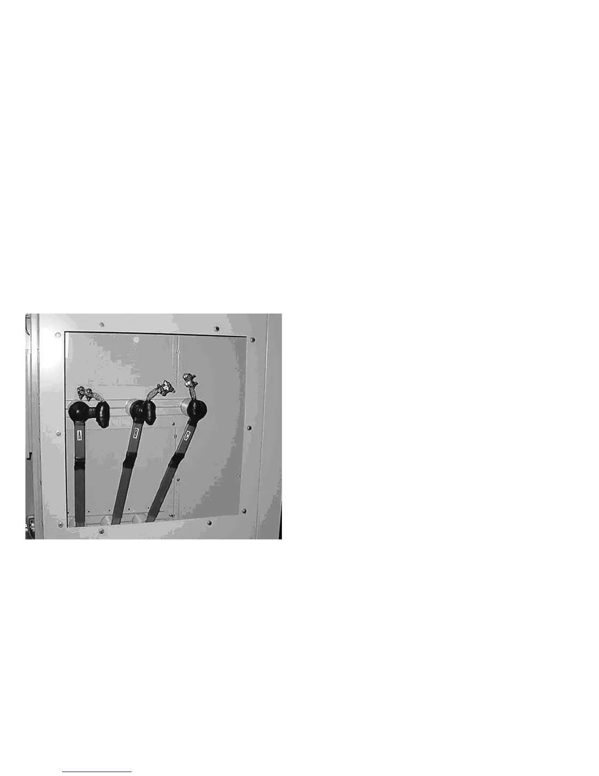
Figure 5. Transformer Connection to the MVS Switch
Medium voltage electrical connections
Connection by cable supplied with the type
MVS switch
•
Cables are NOT factory pre-cut to the proper length. The installer
MUST cut them to fit.
•
Factory cables are unshielded. For 15 kV, 27kV, and 38 kV
applications, they must be properly separated from each
other, from all grounded metal parts, and from the transformer
bushings/terminals of other phases. For 4.76 kV applications,
it is only necessary to install the cables so they will not be
damaged by sharp edges, points, etc.
•
Phasing of the main conductors in type MVS switchgear conforms
to industry standards: that is 1, 2, 3, front to rear, top to bottom,
and left to right at the connection points unless otherwise noted
on the drawings. The installer is responsible for maintaining the
continuity of phasing throughout the system.
•
Lugs are provided with the switchgear for terminating cables
to the transformer bushings/terminals.
Connection by busbar
•
Splice plates and hardware are provided with the MVS switchgear.
The transformer manufacturer supplies the flexible connector.
•
The busbar is tin- or silver-plated. To ensure a proper electrical
connection, care should be taken to protect the plating from
damage. Refer to “Procedures for joining MVS enclosures at
shipping splits” section on page 5 for details.
Connections to an AMPGARDT medium voltage motor
control center (MCC)
Step 1: Holes are predrilled in the side of the MVS switchgear
structure to match the holes provided in the AMPGARD MCC.
Bolt the MVS switchgear and AMPGARD MCC together using
the hardware furnished with the MVS switchgear.
Step 2: Make the bus connections as per “Connections by busbar”
section above.