9
Notes and warnings
PRC-E Series Instruction Manual MN014003EN August 2015 www.eaton.com
RUN: The RUN LED will blink on and off at regular one
second intervals when the BCB is properly wired and
communicating with the controller. If the RUN LED blinks
twice in succession and is then off for three seconds, there
is a problem with the BCB communication.
ote: N If a BCB is addressed to 0, no addressing, the Run
status LED will indicate as normal. BCB addressing
should be verified if there are issues.
PRC-E Series controller wiring
The PRC-E controller handles the communication of direct
controllable circuit breaker command and status through
the onboard SLAN port. In addition to controlling circuit
breakers, the PRC-E Series controller has low voltage inputs
and outputs, which can be used for switches, occupancy
sensors, photocells, dimmable fluorescent ballasts, and
LED drivers.
To access the controller low voltage compartment, loosen
the two LCD display captive screws (Figure 15) until the
unit can be opened downward using the hinge on the
bottom. It is recommended that the power switch be placed
in the OFF position before any wiring is pulled into this
compartment or before any connections are made.
ote: N It is not recommended that the LCD display be
fully removed, however, if it must be fully removed;
consult the PRC technical support line to receive
assistance with removal and the reinstall.
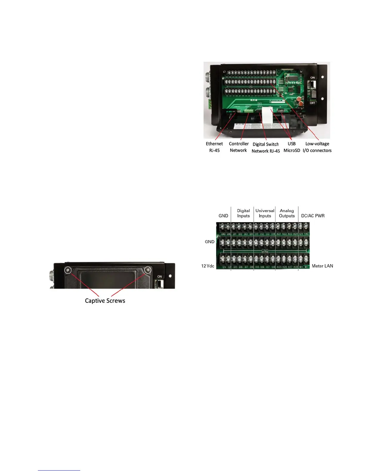
Figure 15. Low Voltage Compartment Access
Located in the low voltage compartment are the connectors
for Ethernet (PRC2000E and PRC1500E only), Controller
Network (CNET) (not available on PRC750E), Digital Switch
Network (DSN) (not available on PRC750E), Micro SD, and
low voltage I/O. For more information on the Ethernet and
Controller Network (CNET) connections, see the “Network
overview” section on page 12. For more information on
the DSN, see the “Digital Switch” section on page 81.
The USB port is for system level storage. The Micro SD card
is used for programming backup and historical data storage.
Figure 16. PRC-E Class 2 Wiring Compartment
There are also three rows of screw-terminal connector
strips. These rows are combined into logical blocks as
illustrated in Figure 17.
Figure 17. Low Voltage Wiring Terminals
Low voltage inputs and outputs
Each PRC-E Series controller has a number of low voltage
input and output connections. These general purpose
points can be used for a variety of applications including
override switches, dimmable fluorescent ballasts and LED
drivers, photocell dry-contact, photosensors analog level
for daylight harvesting, rheostats, occupancy sensors, and
for interfacing with other control systems like security
or building control. In addition to the input and output
terminations, the controllers also provide terminals for
external device supply power. There is a terminal for the
power supply voltage (PWR) for convenient connection
to the 30 Vac or Vdc supply power (1 A max.) and 12 Vdc
terminals (12 V) that have a maximum of 500 mA available.
Each group of input, output, and power points is labeled
in Figure 17 and each group is discussed separately in
the following sections. Also, be aware that this topic is
purposely kept generic due to the many different possible
applications.