11
Notes and warnings
PRC-E Series Instruction Manual MN014003EN August 2015 www.eaton.com
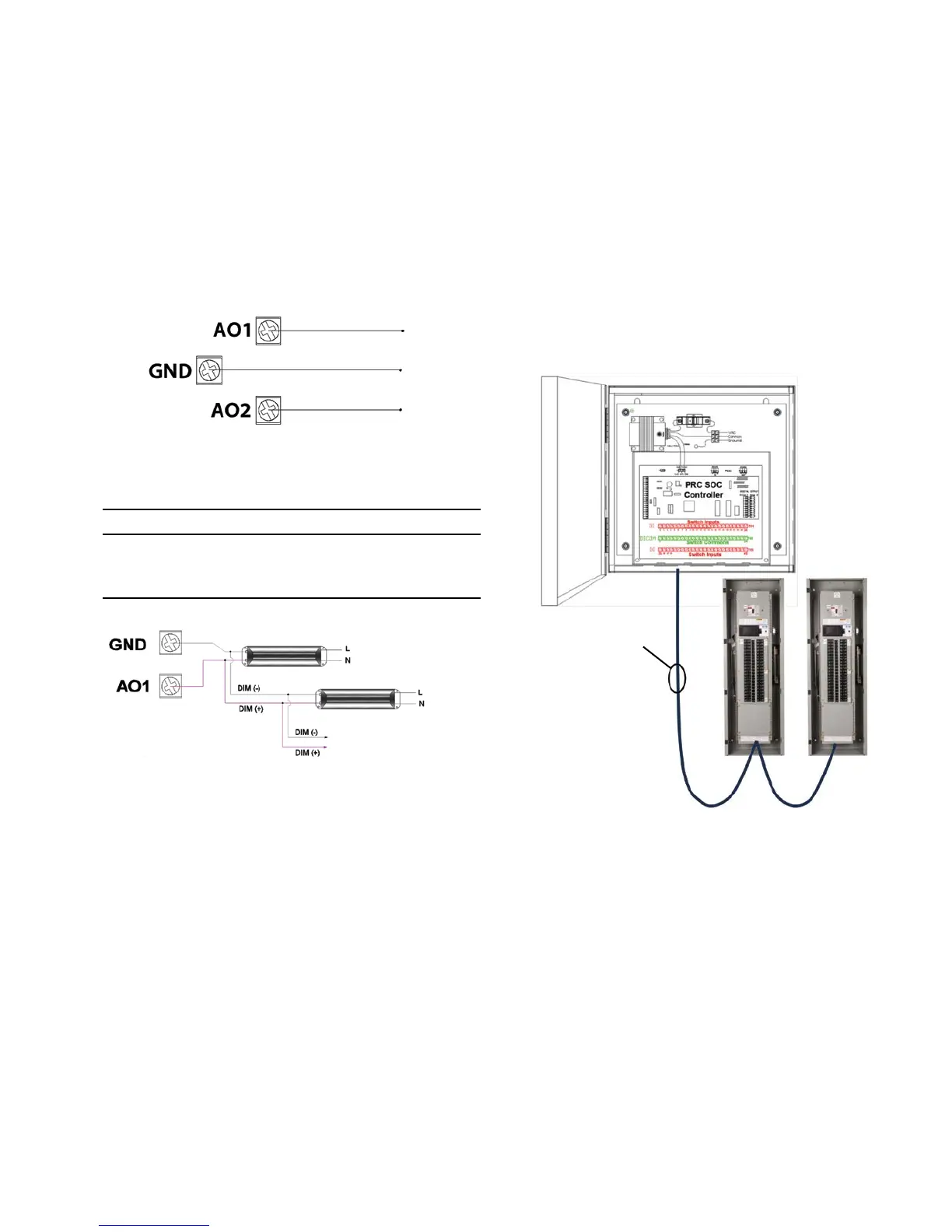
Analog outputs
Analog output points are used as control for dimmable
fluorescent ballasts and dimmable LED drivers. The output
is 0–10 Vdc with a maximum current of 80 mA sink or
maximum 40 mA source. Consult fluorescent ballast and LED
driver data sheets or with the manufacturers of the products
for maximum current requirements for the device prior to
purchase and install. For compatibility verification, please
contact the Eaton Lighting Control Technical Support group.
The above schematic demonstrates the connection of the
analog output.
m CAUTION
TO AVOID DAMAGE TO THE PRCE CONTROLLER OUTPUTS OR
OTHER EQUIPMENT, THE NEGATIVE (–) CONNECTION SHOULD BE
COMPLETED PRIOR TO THE POSITIVE (+) CONNECTION OF THE
ANALOG OUTPUT.
0–10 V dimming fluorescent ballast or LED driver connection
to analog output.
Switch Override Controller
The Pow-R-Command Switch Override Controller (PRCSOC)
can be used to connect digital and analog I/O to PRC
systems. This device is recommended when controller
onboard digital and analog I/O has been exceeded or
when there is an advantage to connecting remote I/O via
a RS-485 network connection. The PRCSOC is supplied
with the controller, termination board, 120/277 Vac
power supply in a NEMA 1 enclosure (consult factory for
alternative methods of adding digital and analog I/O).
Figure 18. Switch Override Controller in
External Cabinet
0–10 Vdc (max. 80 mA sink
40 mA source)
0–10 Vdc (max. 80 mA sink
40 mA source)
Up to max 80 mA sink or
40 mA source per output
PRC RS-485 (CNET)
Belden 3105A Shielded
twisted pair