IB131006EN
Page vi
Effective 07/2017
FIGURES
Figure Title Page
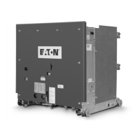
1-1 Type VCP-W and Type VCPW-SE Circuit Breaker Outlines and Dimensions in inches ........................... 8
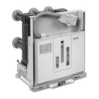
1-2 Type VCPW-ND Circuit Breaker Outlines and Dimensions in inches........................................................ 9
3-1 Typical VCP-W Tools and Accessories ................................................................................................... 14
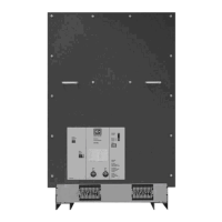
3-2 Typical Front View VCP-W Vacuum Circuit Breaker Element .................................................................. 15
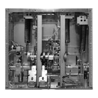
3-3 Typical VCP-W Vacuum Circuit Breaker Element with Front Cover Removed ....................................... 16
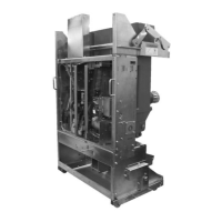
3-4 Typical Rear View VCP-W Vacuum Circuit Breaker Element ................................................................... 17
3-5 Typical VCP-W Vacuum Circuit Breaker Element Escutcheon ............................................................... 18
4-1 Type VCP-W Circuit Breaker Manual Charging Handle in Use ................................................................ 19
4-2A VCP-W Circuit Breaker Pan Assembly .................................................................................................... 21
4-2B VCP-W Circuit Breaker BPI Pan Assembly ............................................................................................. 22
4-3 Engaging Extension Rails in a Lower Circuit Breaker Compartment ....................................................... 22
4-4 Typical VCP-W Circuit Breaker Bottom View ........................................................................................... 22
4-5 Pulling Secondary Disconnect Cage to Engage Secondaries in TEST Position ..................................... 23
4-6 Engaging Levering-In Crank ..................................................................................................................... 23
5-1 Typical VCP-W Rear View Showing Vacuum Interrupters and Current Carrying System ....................... 25
5-2 Graphic Representation of Arc Interruption ............................................................................................. 26
5-3 Closing Cam and Trip Linkage ................................................................................................................. 29
5-4 Charging Schematic ................................................................................................................................. 30
5-5 Typical VCP-W DC and AC Control Schemes .......................................................................................... 32
5-5A Typical VCP-W (VCP-WXC) DC Control Scheme and Diagram .............................................................. 33
5-6 Undervoltage Trip Device Configuration ................................................................................................... 35
6-1 Lubrication Points ..................................................................................................................................... 38
6-1b 150 VCP-W 63 63kA Pole Unit ................................................................................................................. 38
6-2 Vacuum Interrupter Showing Contact Erosion Indicator with Breaker Open ........................................... 41
6-3 Vacuum Interrupter Showing Contact Erosion Indicator with Breaker Closed ......................................... 41
6-4 Wipe Indication Procedure ....................................................................................................................... 42
6-5 Status Indicators ....................................................................................................................................... 43
6-6 Starting Tape at Bottom of Cam .............................................................................................................. 44
6-7 Wrapping Tape Up Around Cam .............................................................................................................. 44
6-8 Attaching Tape Around to Back of Cam ................................................................................................... 44
6-9 Attaching CloSure
TM
Test Tool at Hole “A” .............................................................................................. 44
6-10 Attaching CloSure
TM
Test Tool at HP ........................................................................................................ 45
6-11 Manually Charging Closing Strips ............................................................................................................. 45
6-12 Manually Closing Circuit Breaker with Marker in Hole “C” ........................................................................ 45
6-13 Top View of CAM and Marker Interface .................................................................................................... 45
6-14 Move Marker 15° to Right ......................................................................................................................... 45
6-15 Move Marker 15° to Left ........................................................................................................................... 46
6-16 Remove Marker Masking Tape from Cam ................................................................................................ 46
6-17 Place Tape on Right Side Panel of Breaker ............................................................................................. 46
6-18 Illustrative Testing Tape Sample .............................................................................................................. 46
6-19 Front View of CloSure
TM
Tool Showing Mounting/Testing Hole Locations .............................................. 46
6-20 Typical Circuit Breaker Font View with CloSure
TM
Tool Attached ............................................................ 47
Courtesy of NationalSwitchgear.com

 Loading...