IB131006EN
Page 50
Effective 07/2017
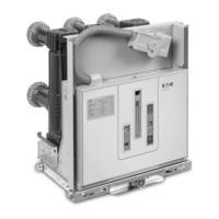
Figure 6-10 Attaching Closure
Test Tool at HP
Step 5 - Mount the transparent CloSure
TM
Test Tool with
two bolts and washers. Refer to Figures 6-19, 6-20 and
Table 6.4 for appropriate mounting holes. Hand tighten
the bolts (Figures 6-9, 6-10, 6-19 and 6-20).
Step 6 - A Sanford
®
Sharpie
®
black fine point permanent
marker, item no. 30001, is recommended for this next
step. Place the marker tip in the proper hole (“C”). Refer
to Figure 6-19 and make a heavy mark on the tape as
shown in Figure 6-10.
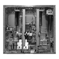
Figure 6-11 Manually Charging Closing Springs
Step 7 - Charge the closing springs with the
maintenance tool. Continue charging the closing springs
until a “click” is heard and the status indicator shows
“Charged” (Figure 6-11).
Step 8 - While holding the marker tip on the tape, close
the breaker (Figure 6-12).
Step 9 - Move the marker back and forth horizontally
approximately 15
in both directions to create a line on
Figure 6-12 Manually Closing Circuit Breaker with
Marker in Hole “C”.
Figure 6-13 Top View of Cam and Marker interface
Figure 6-14 Move Marker 15
o
to Right
the tape that identifies the closed rest position (Figures
6-13, 6-19 and 6-15).
Courtesy of NationalSwitchgear.com

 Loading...