Do you have a question about the Eaton XN-312-GW-CAN and is the answer not in the manual?
| Product Name | Eaton XN-312-GW-CAN |
|---|---|
| Category | Gateway |
| Communication Protocol | CAN |
| Manufacturer | Eaton |
| Model | XN-312-GW-CAN |
| Product Type | Gateway |
Lists significant amendments introduced since previous issues.
Manual is intended for automation technicians and engineers.
Disclaimer regarding information accuracy, liability, and safe operation.
Explains abbreviations and designations used in the manual.
Explains symbols and conventions used in the manual for warnings and tips.
Describes the gateway's function to connect a PLC to a system bus via CANopen.
Explains the gateway's role in connecting I/O modules and its config check feature.
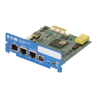
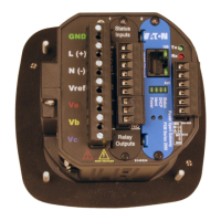
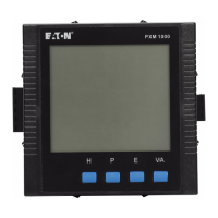
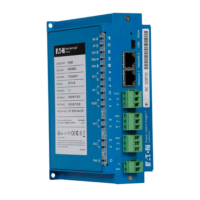
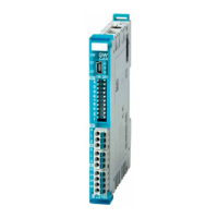
Provides a visual overview and description of the gateway's front view components and terminals.
Lists available XN300 slice modules that can be combined with the gateway.
Details crucial data for engineering, including field bus connection and data volumes.
Instructions for setting the gateway's address using DIP switches before mounting.
Details on setting the gateway's baud rate using DIP switches or automatic detection.
Instructions on activating the integrated bus termination resistor via DIP switch 10.
Prerequisites and steps for mounting the gateway and system block onto the DIN-rail.
Step-by-step guide on how to safely remove the gateway and XN300 slice modules.
Explains the common supply voltage and galvanic isolation within the XN300 system.
Details on connecting the 24 V DC voltage to the gateway's X3 terminals and safety precautions.
Instructions for connecting the CANopen field bus cable to the gateway's X1 interface.
Explains how to use the Mini-USB port for connecting to a computer for diagnostics and updates.
Provides a diagram illustrating the connection example for the XN-312-GW-CAN gateway in the XN300 system.
Outlines EMC measures for minimizing undesired faults on the field bus.
Steps for putting the system bus into operation, including configuration checks.
Steps for putting the CANopen field bus into operation, including PLC programming.
Explains the meaning of the LED statuses on the gateway and I/O slice modules.
States that modules do not send alarms, and diagnostic data is transmitted via PDO or SDO access.
Lists functions of the XN300-Assist program for planning and commissioning.
Details on finding and using standard EDS files, emphasizing version matching.
Explains how to generate a project-specific EDS file using XN300-Assist for custom configurations.
Provides procedures for installing EDS files in XSoft-CoDeSys-2 and XSOFT-CODESYS-3.
Details the initial connection steps for a PLC with configuration software.
Step-by-step guide for configuring the system using XSOFT-CODESYS-2 with specific devices.
Step-by-step guide for configuring the system using XSOFT-CODESYS-3 with specific devices.
Provides an overview of supported CANopen objects and their static entries in the dictionary.
Details objects related to the XN300 station, including device type and names.
Explains the object 1001hex for accessing the gateway's internal faults and error register.
Describes objects for monitoring node readiness using heartbeat and guarding protocols.
Covers objects related to SYNC COB-ID and EMCY COB-ID for synchronization and error messages.
Details object 1200hex for server SDO parameters affecting SDO1 transmission priority.
Explains objects 1400hex to 140Fhex that define priority and transmission type for RPDO transfers.
Covers objects 1800hex to 180Fhex defining priority, inhibit time, and transmission type for TPDO transfers.
Describes digital input objects and manufacturer-specific objects for the 8DI-PD module.
Details digital input objects and manufacturer-specific objects for the 16DI-PD module.
Covers digital input objects and manufacturer-specific objects for the 20DI-PD module.
Explains digital input objects and manufacturer-specific objects for the 20DI-PF module.
Details digital input objects and manufacturer-specific objects for the 20DI-PCNT module.
Covers digital input objects and manufacturer-specific objects for the 20DI-ND module.
Explains digital output objects and manufacturer-specific objects for the 4DO-RNO module.
Details digital output objects and manufacturer-specific objects for the 8DO-P05 module.
Covers digital output objects and manufacturer-specific objects for the 12DO-P17 module.
Explains digital output objects and manufacturer-specific objects for the 16DO-P05 module.
Details digital input/output objects and manufacturer-specific objects for the 8DIO-PD05 module.
Covers digital input/output objects and manufacturer-specific objects for the 16DIO-PD05 module.
Explains digital input/output objects and manufacturer-specific objects for the 16DIO-PC05 module.
Details analog input objects and manufacturer-specific objects for the 4AI-PTNI module.
Covers analog input objects and manufacturer-specific objects for the 7AI-U2PT module.
Explains analog input objects and manufacturer-specific objects for the 8AI-I module.
Details analog input objects and manufacturer-specific objects for the 10AI-TEKT module.
Covers analog output objects and manufacturer-specific objects for the 8AO-U2 module.
Explains analog input/output objects and manufacturer-specific objects for the 4AIO-U2 module.
Details analog input/output objects and manufacturer-specific objects for the 8AIO-U2 module.
Covers analog input/output objects and manufacturer-specific objects for the 4AIO-I module.
Explains analog input/output objects and manufacturer-specific objects for the 8AIO-I module.
Covers analog input objects and manufacturer-specific objects for the 2DMS-WM module.
Details PWM output objects and manufacturer-specific objects for the 1DCD-B35 module.
Explains encoder objects and manufacturer-specific objects for the 1CNT-8DIO module.
Covers SSI objects and manufacturer-specific objects for the 2SSI module.
Defines key terms like Station Variants, Full Configuration, Reduced Assembly, Actual Configuration, Target Configuration.
Explains the benefits of the station variants mode for flexible XN300 system configurations.
Details the two initialization phases and the gateway's behavior in station variants mode.
Describes the XN300-Assist program's functions and compatibility with station variants.
Provides steps for installing new firmware onto the gateway using XN300-Assist.
Lists CAN objects related to station variants, including activation and checksum.
Lists product standards, UL file numbers, NA certification, and degree of protection.
Provides physical dimensions of the XN-312-GW-CAN gateway including H x D x W and mounting details.
Lists technical specifications for the gateway including general, environmental, and electrical data.
Lists available XN-322 slice modules for the XN300 system.
Specifies supported firmware and EDS file versions for XN-322 modules.
Details the maximum number of RPDO and TPDO for the gateway.