Do you have a question about the Eaton XNE-GWBR-2ETH-MB and is the answer not in the manual?
Explains the manual's scope and related documents for the XI/ON gateway.
Details warning, attention, and note symbols used throughout the manual.
Provides a general overview of the gateway, its prescribed use, and planning/installation notes.
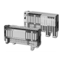
Introduces the XI/ON system as a modular I/O solution for industrial automation.
Details the various components of the XI/ON system, including gateways, modules, and accessories.
Explains the Ethernet system, MAC-ID, IP addressing, network classes, and data transfer principles.
Provides a general technical overview of the gateway, independent of its protocol.
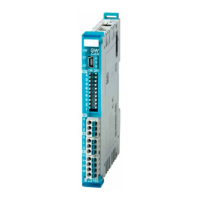
Describes the gateway's role as a connection between XI/ON modules and the Ethernet network.
Presents detailed technical specifications including system extension, electrical data, and physical interfaces.
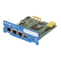
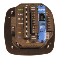
Details the physical connection options for power supply and field bus interfaces on the gateway.
Explains default settings and various methods for configuring the gateway's network address.
Describes the procedure for saving the current XI/ON station configuration to the gateway's non-volatile memory.
Explains the gateway's diagnostic messages and status indicators displayed via LEDs.
Provides a fundamental description of the Modbus protocol and its implementation.
Lists the Modbus functions supported by the XI/ON gateway for accessing data and services.
Details the Modbus register mapping for the gateway, including addresses and descriptions.
Explains how module data is packed and mapped into register areas for efficient access.
Shows the data width of various XI/ON I/O modules and their alignment in Modbus registers.
Describes the service-object used for executing one-time or acyclic services like module parameterization.
Explains how digital inputs and outputs are mapped into registers for reading and writing single bits.
Details how outputs behave in case of Modbus communication failure, based on watchdog settings.
Covers the detailed parameters for various analog, digital, technology, and communication modules.
Lists diagnostic messages for different module types, including power supply, analog, digital, and technology modules.
Explains the basic network configuration and IP addressing for communication.
Guides through changing IP addresses in Windows 2000/XP and Windows NT for network connectivity.
Presents practical examples of Modbus TCP communication and telegram interpretation.
Provides examples of how to parameterize XI/ON I/O modules via register access.
Explains how to interpret diagnostic data from XI/ON modules, including group diagnosis.
Covers module arrangement possibilities, combinations, and random placement within a station.
Details the limits and factors for extending an XI/ON station, including module count and current consumption.
Explains the gateway's integrated power supply and the concept of module bus refreshing.
Advises on protecting the service interface and DIP-switches from EMC and ESD.
Explains how to download firmware to the gateway using the I/O-ASSISTANT software.
Provides general guidelines for cable grouping, routing, and EMC compatibility.
Describes the potential relationships within an Ethernet system using XI/ON modules.
Details requirements for electromagnetic compatibility, grounding, and earthing.
Covers the principles and methods for effective cable shielding to prevent interference.
Discusses potential differences and the use of compensation cables and ESD protection.
Details the data image structure for technology modules like counters, PWM, and communication interfaces.
Lists the module-specific ident codes used by the gateway for identifying XI/ON modules.
Provides definitions for technical terms used throughout the manual.
| Model | XNE-GWBR-2ETH-MB |
|---|---|
| Category | Gateway |
| Ethernet Ports | 2 |
| Power Supply | 24 V DC |
| Communication | Modbus RTU, Modbus TCP |