9
EN
EN
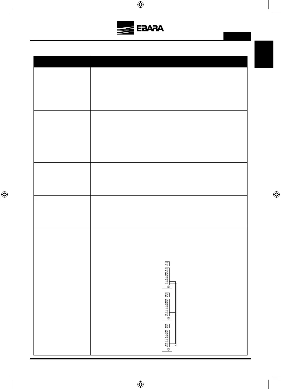
FRECUENCY CONVERTER 2
1
2
FRECUENCY CONVERTER 1
1
2
FRECUENCY CONVERTER 8
1
2
b) Signal connections
Outputs relay 1 and 2
Outputs that act according to how the parameters 5.14 and 5.15 respectively have been
programmed.
These outputs are potential free and have a maximum load of 5 amperes at 230 Vac.
When wall-mounted, as there is no cooling from the motor’s own fan, the ventilation
system of the wall mounting shall be used for this cooling.
This output is 24 Vdc and it is activated whenever the frequency converter is giving a
voltage output; its maximum load is 9 W.
You can connect any potential free contact that will perform the functions programmed in
parameters 5.12 and 5.13 respectively to these inputs.
NOTE: Do not apply voltage to these inputs!
Connection of the pressure transducer (always 4-20 mA), maintaining the correct polarity
shown in the connections diagram of the transducer itself.
Fan
Digital inputs 1 and 2
Transducer
The various frequency converters that you wish to communicate should be interconnected
at these terminals (maximum 8). They are connected point to point. The “1” terminals
must be connected together in the same way as the “2” terminals.
RS485 communication
Signal Description
 Loading...