Page | 10
This document is proprietary. No disclosure, reproduction or use of any part thereof may be made without the expressed
written permission of Ebbco Inc. or its subsidiaries.
Section 3: System Installation and Operation Procedures
3.3 Heat Exchanger Installation Procedure
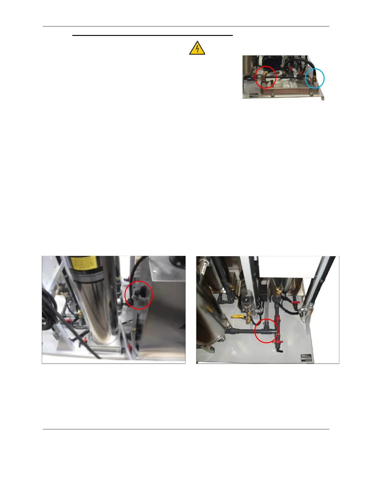
To connect pre-existing cooling unit to heat exchanger:
1) Remove the white caps protecting the threads on the 1.0” inlet and
outlet threads.
2) Connect pluming from the customer’s preexisting cooling device
discharge to the 1.0” fluid inlet on the heat exchanger (red circle).
3) Connect plumbing from the heat exchanger 1.0” fluid outlet (blue
circle) to the customer’s preexisting cooling device inlet.
3.4 Chiller Installation Procedure
To install a 90K in-line chiller unit:
1) Remove the ¾” hose from the chiller inlet and outlet hose barbs on the CLS (see right and below right
images).
2) There are two lengths of provided hose to connect the chiller to the CLS. Connect the CLS to the in-
line chiller as follows:
a. Attach one length of hose to the 0.75” hose barb inlet located on the CLS tank (see Figure 3.1).
Connect the opposite end of that hose to the 0.75” hose barb on the in-line chiller marked fluid
outlet from chiller.
b. Attach the second length of hose to the 0.75” hose barb outlet on the CLS base (see Figure 3.2).
Connect the opposite end of that hose to the 0.75” hose barb on the in-line chiller marked fluid
inlet to chiller.
Figure 3.2
Chiller Outlet (to chiller) Connection
Figure 3.1
Chiller Inlet (from chiller) Connection