VEHICLE HEATERS – TECHNICAL DOCUMENTATION | 9
2 INSTALLATION
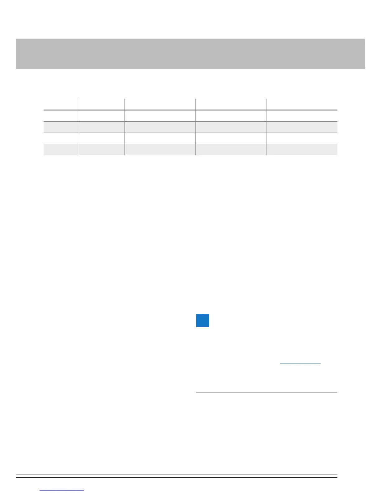
-XS4 / -XB4 CONNECTOR ASSIGNMENT TABLE
Pin Signal Cable colour Cross-section XS4 Cross-section XB4
1 Terminal 30 red 0.35 mm² 0.5 mm²
2 Terminal 58 grey / black 0.35 mm² 0.5 mm²
3 Terminal 31 brown 0.35 mm² 0.5 mm²
4 Diagnosis blue / white 0.35 mm² 0.5 mm²
INSTALLATION SKETCH KEY
1 EasyStart Select 12 / 24 volt
2 Cover
3 Foam underlay
4 Connector housing, 4 pin
5 Bush housing, 4 pin
6 Contact locking devices
7 Contacts
8 Self-tapping screw
9 Template
10 Heater lead harness
CONNECTION OF BUSH HOUSING TO THE
CONTROL UNIT LEAD HARNESS
Clip the control unit lead harness into the
4-pin bush housing; note and follow the
circuit diagram.
Push the contact locking device into the
bush connector housing.
Connect the bush housing of the control
unit lead harness and the connector hous-
ing of the EasyStart Select lead harness.
Insulate and tie back any cable ends that
are not needed.
PLEASE NOTE!
Install the EasyStart Select in the vehicle
interior only.
For circuit diagrams see from page 15.
Do not insert the 5 A fuse into the fuse
holder until all work has been completed.
 Loading...