EasyManua.ls Logo

ebm-papst R3G560-RB32-01 - User Manual

ebm-papst R3G560-RB32-01
12 pages
Print Icon
To Next Page IconTo Next Page
Loading...
Operating instructions
R3G560-RB32-01
Translation of the original operating instructions
ebm-papst Mulfingen GmbH & Co. KG
Bachmühle 2
D-74673 Mulfingen
Phone +49 (0) 7938 81-0
Fax +49 (0) 7938 81-110
info1@de.ebmpapst.com
www.ebmpapst.com
CONTENTS
1. SAFETY REGULATIONS AND NOTES
11. SAFETY REGULATIONS AND NOTES
Please read these operating instructions carefully before starting to work
with the device. Observe the following warnings to prevent malfunctions
or physical damage to both property and people.
These operating instructions are to be regarded as part of this device.
If the device is sold or transferred, the operating instructions must
accompany it.
These operating instructions may be duplicated and forwarded for
information about potential dangers and their prevention.
1.1 Levels of hazard warnings
11.1 Levels of hazard warnings
These operating instructions use the following hazard levels to indicate
potentially hazardous situations and important safety regulations:
DANGER
Indicates an imminently hazardous situation which, if not
avoided, will result in death or serious injury. Compliance with
the measures is mandatory.
WARNING
Indicates a potentially hazardous situation which, if not avoided,
could result in death or serious injury. Exercise extreme
caution while working.
CAUTION
Indicates a potentially hazardous situation which, if not avoided,
may result in minor or moderate injury or damage of property.
NOTE
A potentially harmful situation can occur and, if not avoided, can
lead to property damage.
1.2 Staff qualification
11.2 Staff qualification
The device may only be transported, unpacked, installed, operated,
maintained and otherwise used by qualified, trained and authorised
technical staff.
Only authorised specialists are permitted to install the device, to carry
out a test run and to perform work on the electrical installation.
1.3 Basic safety rules
11.3 Basic safety rules
Any safety hazards stemming from the device must be re-evaluated
once it is installed in the end device.
Observe the following when working on the unit:
; Do not make any modifications, additions or conversions to the
device without the approval of ebm-papst.
1.4 Electrical voltage
11.4 Electrical voltage
; Check the electrical equipment of the device at regular intervals, refer
to chapter 6.2 Safety test.
; Replace loose connections and defective cables immediately.
WARNING
Terminals and connections have voltage even with a
unit that is shut off
Electric shock
Wait five minutes after disconnecting the voltage at all poles
before opening the device.
CAUTION
In the event of failure, there is electric voltage at the
rotor and impeller
The rotor and impeller are base insulated.
Do not touch the rotor and impeller once they are installed.
21.5 Safety and protective functions
21.6 Electromagnetic radiation
21.7 Mechanical movement
21.8 Emission
21.9 Hot surface
21.10 Storage
21.11 Disposal
32. PROPER USE
43. TECHNICAL DATA
43.1 Product drawing
53.2 Nominal data
53.3 Data according to ErP directive
53.4 Technical features
53.5 Mounting data
53.6 Transport and storage conditions
63.7 Electromagnetic compatibility
64. CONNECTION AND START-UP
64.1 Connecting the mechanical system
64.2 Connecting the electrical system
74.3 Connection in terminal box
84.4 Factory settings
94.5 Connection screen
104.6 Checking the connections
104.7 Switch on device
104.8 Switching off the device
105. INTEGRATED PROTECTIVE FUNCTIONS
116. MAINTENANCE, MALFUNCTIONS, POSSIBLE
CAUSES AND REMEDIES
116.1 Cleaning
126.2 Safety test
Item no. 52110-5-9970 · ENG · Revision 85863 · Release 2015-06-26 · Page 1 / 12
ebm-papst Mulfingen GmbH & Co. KG · Bachmühle 2 · D-74673 Mulfingen · Phone +49 (0) 7938 81-0 · Fax +49 (0) 7938 81-110 · info1@de.ebmpapst.com · www.ebmpapst.com
Question and Answer IconNeed help?

Do you have a question about the ebm-papst R3G560-RB32-01 and is the answer not in the manual?

Summary

Safety Regulations and Notes

Levels of Hazard Warnings

Explains hazard level indicators like DANGER, WARNING, CAUTION, NOTE.

Staff Qualification Requirements

Specifies that only qualified and trained personnel should operate or maintain the device.

Basic Safety Rules

Outlines general safety rules to follow when working on the unit and modifications.

Electrical Voltage Safety

Warns about electrical voltage presence even when the unit is shut off and safety precautions.

Proper Use Guidelines

Safety and Protective Functions

Details dangers of missing or malfunctioning safety devices and required protection.

Electromagnetic Radiation and EMC

Discusses potential interference and EMC compliance for electromagnetic radiation.

Mechanical Movement Hazards

Covers hazards related to rotating parts and flying parts due to mechanical movement.

Noise Emission Precautions

Addresses potential noise levels and necessary precautions for hearing protection.

Hot Surface Burn Risk

Warns about high temperatures and the risk of burn injuries from the electronics enclosure.

Storage Guidelines

Provides guidelines for storing the device in a dry, weatherproof, and clean environment.

Disposal Instructions

Instructs to comply with national regulations when disposing of the device.

Prohibited Improper Uses

Lists prohibited uses that may cause hazards, like operating with imbalance or in explosive atmospheres.

Technical Data Overview

Product Drawing and Dimensions

Presents a detailed technical drawing of the product with dimensions and specifications.

Nominal Motor Data

Provides detailed technical specifications for the motor, including voltage, frequency, power, and temperature limits.

ErP Directive Data

Lists efficiency data and power consumption figures according to the ErP directive.

Key Technical Features

Details the physical and electrical characteristics of the device, such as mass, material, and protection type.

Mounting Screw Specifications

Specifies requirements for mounting screws and general mounting advice.

Transport and Storage Temperature Limits

Outlines the permissible ambient temperatures for transport and storage.

Electromagnetic Compatibility Standards

States compliance with EMC standards for immunity and emission.

Connection and Start-Up Procedures

Mechanical System Connection

Provides safety precautions for handling and connecting the mechanical parts of the device.

Electrical System Connection

Details electrical connection safety, insulation requirements, and wiring precautions.

Electrical Connection Prerequisites & Power Supply

Checks for connection, supply voltage, and fuse protection requirements.

Electrical Connection Notes

Details idle current, RCD, leakage, and locked-rotor protection notes.

Terminal Box Cable Preparation

Guides on preparing and connecting lines within the terminal box, including stripping lengths.

Connecting Cables to Terminals

Guides on connecting cables to terminals, emphasizing safety precautions like waiting for voltage discharge.

Cable Routing Best Practices

Provides instructions on routing cables to prevent water penetration and ensure proper gland arrangement.

Factory Default Settings

Lists the default factory settings for control modes, parameters, and functions.

Connection Screen Terminal Assignments

Details the connection terminals, their designations, and functions for mains supply, status relay, and control interfaces.

Checking Electrical Connections

Outlines steps for checking connections, ensuring power is off, and securing the terminal box.

Device Switch-On Procedure

Provides instructions and warnings for switching on the device after installation and connection.

Device Switch-Off Procedure

Explains procedures for switching off the device during operation and for maintenance.

Integrated Protective Functions

Integrated Protective Function Details

Describes malfunctions like rotor errors or phase failure and their protective functions.

Maintenance, Malfunctions, and Remedies

Troubleshooting Malfunctions and Causes

Lists common malfunctions, their possible causes, and recommended remedies.

Addressing Insufficient Cooling

Explains how to address insufficient cooling and reset error messages.

Managing High Ambient Temperatures

Describes how to manage high ambient temperatures and reset associated errors.

Correcting Operating Point Issues

Guides on correcting operating points and resetting errors related to excessive counterpressure.

Safe Cleaning Procedures

Provides instructions and warnings for cleaning the device safely, avoiding water jets and harsh chemicals.

Periodic Safety Test Procedures

Overview

This document provides operating instructions for the R3G560-RB32-01 device, a built-in component designed for conveying air. It emphasizes safety regulations, proper use, technical specifications, connection procedures, integrated protective functions, and maintenance guidelines.

Function Description

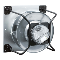
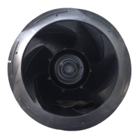
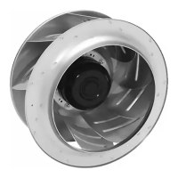
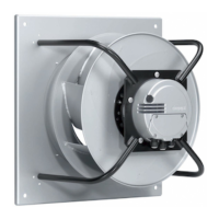
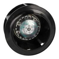
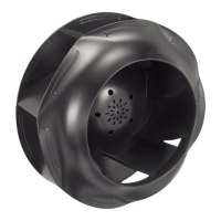
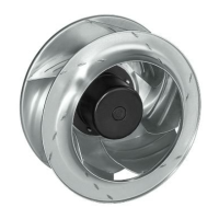
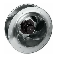
The R3G560-RB32-01 is an EC centrifugal fan with a backward-curved impeller, designed for use as a built-in component in systems for conveying air. It operates as a variable speed drive, offering PWM controlling capabilities. The device is intended for stationary systems and moves air with a density of 1.2 kg/m³. It features an integrated PID controller, soft start functionality, and various protective features to ensure safe and reliable operation. The fan is equipped with an RS485 MODBUS RTU interface for communication and control, allowing for integration into broader control systems. It also includes an alarm relay and outputs for operation and alarm display, as well as inputs for sensors and external release.

Important Technical Specifications

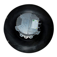
Motor: M3G150-IF Phase: 3~ Nominal Voltage: 400 VAC (range 380-480 VAC) Frequency: 50/60 Hz Speed: 1650 min⁻¹ Power Input: 2900 W Current Draw: 4.43 A Min. Ambient Temperature: -25 °C Max. Ambient Temperature: 50 °C Mass: 27.8 kg Size: 560 mm Surface of Rotor: Coated in black Material of Electronics Housing: Die-cast aluminium Material of Impeller: PP plastic Number of Blades: 6 Direction of Rotation: Clockwise, seen on rotor Type of Protection: IP 54 Insulation Class: "F" Humidity Class: F4-1 Mounting Position: Shaft horizontal or rotor on bottom; rotor on top on request Condensate Discharge Holes: Rotor-side Operation Mode: S1 Motor Bearing: Ball bearing Overall Efficiency (nes): 66.9% Efficiency Grade (N): 72.5 Power Input (Ped): 2.93 kW Air Flow (qv): 9440 m³/h Pressure Increase Total (psf): 710 Pa Speed (n): 1655 min⁻¹ Output 10 VDC: max. 10 mA Output 20 VDC: max. 50 mA Output for slave: 0-10 V Input for sensor: 0-10 V or 4-20 mA External 24 V Input: (programming) Motor Current Limit: Yes PFC: Passive Touch Current (IEC 60990): <= 3.5 mA Electrical Leads: Via terminal box Motor Protection: Reverse polarity and locked-rotor protection Protection Class: I (if protective earth is connected by customer) Product Conforming to Standard: EN 61800-5-1; CE Approval: C22.2 Nr.77 + CAN/CSA-E60730-1; UL 1004-7 + 60730 EMC Interference Immunity: Acc. to EN 61000-6-2 (industrial environment) EMC Interference Emission: Acc. to EN 61000-6-4 (industrial environment)

Usage Features

The device is designed for proper use in power systems with earthed neutral (TN/TT power systems). It must be operated with all protective features in place and in accordance with the permitted ambient temperature. The control mode is pre-set to PWM controlling, with parameter sets configurable for specific applications. The device offers analogue inputs (0-10 V or 4-20 mA) for set value control and actual value feedback, as well as digital inputs for enabling electronics, parameter set switching, and controller function selection. A fixed voltage output of 10 VDC and 20 VDC is available for external devices or sensors. The device incorporates integrated protective functions that automatically switch off the motor in case of rotor position detection error, locked rotor, line under-voltage, or phase failure, with automatic restart capabilities once the fault is cleared or conditions return to normal. For cyclic speed loads, the rotating parts are designed for a maximum of one million load cycles. When installing, it is crucial to secure mounting screws against accidental loosening and ensure proper cable routing to prevent water penetration into the cable gland. The terminal box connections must be made carefully, ensuring correct wiring and proper sealing of the box.

Maintenance Features

Maintenance involves regular checks and cleaning to ensure optimal performance and safety. Cleaning:

  • The device should not be cleaned using a water jet or high-pressure washer.
  • Avoid using cleaners containing acids, bases, or solvents.
  • Do not use pointed or sharp-edged objects for cleaning.
  • If the impeller is running roughly due to imbalance from dirt deposits, the device should be cleaned. If imbalance persists, the device should be replaced. Any weight clips attached during cleaning must be removed afterwards. Safety Test (at least every 6 months):
  • Protective casing: Visual inspection for damage; repair or replacement if damaged.
  • Device for damage to blades and housing: Visual inspection for damage; replacement if damaged.
  • Mounting the connection lines: Visual inspection; fasten if loose.
  • Insulation of the wires: Visual inspection for damage; replace wires if damaged.
  • Impeller for wear/deposits/corrosion and damage: Visual inspection; clean or replace impeller if necessary.
  • Tightness of screwed cable gland: Visual inspection; retighten, replace if damaged.
  • Condensate discharge holes: Visual inspection for clogging; open bore holes if necessary. General Maintenance:
  • Do not perform repairs on the device; return it to ebm-papst for repair or replacement.
  • If the device remains out of use for over four months, it is recommended to switch it on for at least three hours at full speed to evaporate any condensate and move the bearings.
  • Before any work on the device, ensure the mains supply voltage is switched off at all poles and secured from being switched on again. Wait five minutes after disconnecting voltage before opening the device.
  • In case of mechanical blockage, switch off, de-energize, and remove the blockage.
  • For faulty connections, de-energize and correct the connection according to the connection diagram.
  • If the motor winding is broken, the device must be replaced.

ebm-papst R3G560-RB32-01 Specifications

General IconGeneral
Brandebm-papst
ModelR3G560-RB32-01
CategoryFan
LanguageEnglish

Related product manuals