Do you have a question about the EBS MICROBASS 3 and is the answer not in the manual?
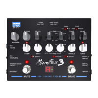
Groups GAIN, TYPE, TONE, DRIVE, LEVEL, MID, and CHARACTER FILTER controls for the drive channel.
Groups BASS, TREBLE, COMP/LIMITER, and BYPASS controls for the clean channel.
Covers BLEND for channel mixing and MASTER for overall output volume.
Details the MUTE and DRIVE FOOT SWITCH functions for silent tuning and channel selection.
Explains the FX SEND & RETURN loop and STEREO MODE ON/OFF for external effects integration.
Details OUTPUT, POST BAL OUT, PRE/POST BAL OUT, and their signal routing options.
Covers DRIVE INPUT, INPUT, AUX IN, and DC INPUT for instrument, auxiliary, and power connections.
Describes the PHONES output for silent practice and GND LIFT switch for noise reduction.
Lists input impedance, gain, character, bright filter, bass, mid, and treble filter details.
Details input impedance, drive, gain range, drive engines, type switch, tone, and mid filter specs.
Covers effects loop, headphone/aux input, outputs, power requirements, dimensions, and weight.
Visual representation of the signal path through the Hi-Z buffer, gain, filters, engines, and master section.
Illustrates the placement of the effects loop, stereo mode switch, and footswitches within the signal chain.
Shows how the signal is routed to balanced outputs, headphones, and auxiliary inputs.
| Input Impedance | 1 MΩ |
|---|---|
| Character Filter | Yes |
| Drive | Yes |
| Compressor | Yes |
| Line Out | Yes |
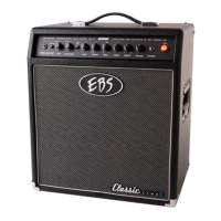
| Speaker Size | 12 inches |
| Inputs | 1 x 1/4" |
| Outputs | 1 x XLR, 1 x 1/4" |
| Equalizer | 4-band EQ |
| Other Features | Headphone Out |
| Power Requirements | 100-240V AC |