Chengdu Ebyte Electronic Technology Co., Ltd. E77-xxxM22S User Manual
Copyright © 2012-2 024 , Chengdu Ebyte Electronic Technology Co., Ltd.
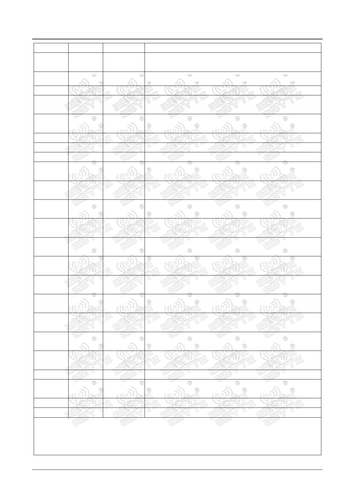
Configurable general-purpose IO port (see STM32WLE5CCU6
manual for details)
LP_ USART 2 _TX (AT command serial port transmission pin)
LP_ USART 2 _RX (AT command serial port receiving pin)
Configurable general-purpose IO port (see STM32WLE5CCU6
manual for details)
Configurable general-purpose IO port (see STM32WLE5CCU6
manual for details)
Ground wire, connected to the power reference ground
Antenna interface, stamp hole (50 Ω characteristic impedance)
Ground wire, connected to the power reference ground
Configurable general-purpose IO port (see STM32WLE5CCU6
manual for details)
Chip reset trigger input pin, active low level (built-in 0.1uF ceramic
capacitor)
Configurable general-purpose IO port (see STM32WLE5CCU6
manual for details)
Configurable general-purpose IO port (see STM32WLE5CCU6
manual for details)
Configurable general-purpose IO port (see STM32WLE5CCU6
manual for details)
Configurable general-purpose IO port (see STM32WLE5CCU6
manual for details)
Configurable general-purpose IO port (see STM32WLE5CCU6
manual for details)
Configurable general-purpose IO port (see STM32WLE5CCU6
manual for details)
Configurable general-purpose IO port (see STM32WLE5CCU6
manual for details)
Configurable general-purpose IO port (see STM32WLE5CCU6
manual for details)
Configurable general-purpose IO port (see STM32WLE5CCU6
manual for details)
Ground wire, connected to the power reference ground
Power supply, ranging from 1.8 to 3.6 V (it is recommended to add
external ceramic filter capacitors)
*The pins in red font are the pins used by the LoRaWAN firmware that comes with the module;
Note 1: The PA6 and PA7 pins are used as internal control radio frequency switches in the module, PA6 =
RF_TXEN, PA7 = RF_RXEN, RF_TXEN=1 RF_RXEN=0 is the sending channel, RF_TXEN=0 RF_RXEN=1 is the
receiving channel