Do you have a question about the Ebyte E22-400T30S and is the answer not in the manual?
Introduces the E22-400T30S wireless serial port module based on SX1268.
Lists key features like communication distance, power, frequency, and technology support.
Explains LoRa, LBT, RSSI, wireless configuration, networking, and power saving.
Details the operational limits for power supply, blocking power, and operating temperature.
Lists operating parameters like voltage, temperature, frequency, power consumption, and data rates.
Details the function, direction, and pin number for each module pin (M0, M1, RXD, TXD, AUX, VCC, etc.).
Shows the electrical connection diagram between the module and a microcontroller (MCU).
Explains how the module performs fixed-point data transmission with address and channel.
Describes broadcasting data transmission using FF FF address for all modules on a channel.
Details setting address to 0xFFFF or 0x0000 for broadcast and monitor functions.
Explains using 0xFFFF or 0x0000 for monitoring data from all modules on a channel.
Describes the module reset process and the role of the AUX pin rising edge.
Explains the function and indication capabilities of the AUX pin for status and self-check.
Explains AUX pin behavior for UART output and waking up the MCU.
Explains AUX pin behavior during wireless transmitting and buffer status.
Details how to switch between operating modes using M1 and M0 pins and AUX status.
Describes the normal mode where UART and wireless communication are active.
Lists the command formats used for configuring the module in configuration mode.
Details registers for module address, network ID, serial port, and air data rate.
Continues description of registers for channel control, RSSI, and WOR control.
Further details on REG2, REG3, including CRYPT_H, CRYPT_L, PID.
Lists the default factory parameters for the E22-400T30S module.
Explains the rules and logic for repeater networking, including forwarding and NETID usage.
Shows the E22-400T30S configuration host computer display interface.
Provides recommendations for power supply, grounding, and voltage stability for reliable operation.
Discusses reasons for short communication range and how to improve it.
Explains common causes of module damage and how to prevent them.
Addresses high Bit Error Rate issues and their potential causes like interference.
Provides temperature profiles for reflow soldering of the module.
Illustrates the temperature profile graph for reflow soldering.
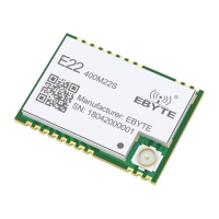
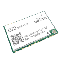
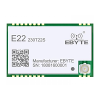
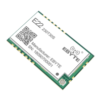
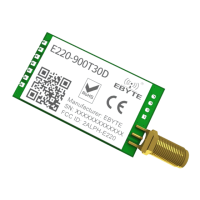
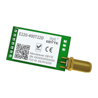
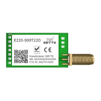
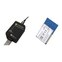
Compares different E22 series models based on core IC, frequency, power, distance, size, and interface.
Lists recommended antennas with their specifications for optimal performance.
| Brand | Ebyte |
|---|---|
| Model | E22-400T30S |
| Category | Wireless modules |
| Language | English |