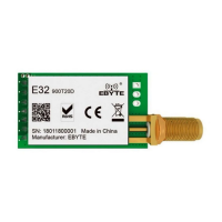
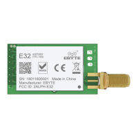
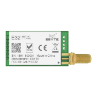
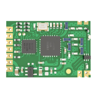
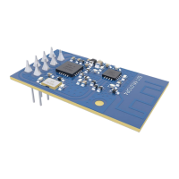
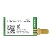
The E32-900T30D is a wireless serial port module (UART) developed by Chengdu Ebyte Electronic Technology Co., Ltd. It is based on SEMTECH's SX1276 RF chip and operates in the 862MHz-931MHz frequency band, utilizing LoRa spread spectrum technology for enhanced communication. The module is designed for various applications requiring long-distance, low-power wireless communication.
Function Description:
The E32-900T30D module supports multiple transmission modes, including fixed transmission and broadcast transmission. In fixed transmission, data is sent to a specific target address and channel. For broadcast transmission, the module can be configured to send data to all modules within a specified channel, or a receiving module can be set to monitor data from all modules on a particular channel.
The module incorporates several features to ensure reliable and efficient communication:
- Advanced LoRa Modulation: Provides long-distance anti-interference capabilities, with a communication range of up to 8km under ideal conditions, outperforming traditional GFSK.
- FEC Forward Error Correction: Enhances communication stability by correcting errors during transmission.
- Air Wake-up (Ultra-low Power Consumption): This feature makes the module suitable for battery-powered applications by allowing it to operate with very low power consumption.
- Data Encryption and Compression: Ensures the confidentiality and efficient transmission of data.
- Channel Monitoring: Allows a module to receive data from all modules on a specific channel, enabling monitoring applications.
- Reset Functionality: When powered on, the AUX pin outputs a low level during hardware self-check and parameter setup. After this process, AUX outputs a high level, indicating normal operation. Users should wait for the AUX rising edge before starting normal module operation.
- AUX Pin Description: The AUX pin serves as an indicator for the wireless send/receive buffer and self-check status. It can signal whether data is pending wireless transmission, if all wireless data has been sent via UART, or if the module is undergoing self-check initialization. This is crucial for synchronizing external MCUs with the module's operational state.
Important Technical Specifications:
- Operating Voltage: 3.3V to 5.5V DC. A power supply greater than 3.3V is recommended for optimal performance. Voltages exceeding 5.5V can cause permanent damage.
- Operating Temperature: Industrial-grade design, supporting long-term use from -40°C to +85°C.
- Operating Frequency: 862MHz to 931MHz, supporting the 868/915MHz EU general frequency band.
- Maximum Transmit Power: 30dBm, with multi-level adjustable software settings.
- Receiving Sensitivity: -148dBm (at an air data rate of 2.4kbps).
- Data Transmission Rate: Configurable from 0.3kbps to 19.2kbps. Lower air data rates generally result in longer transmission distances and better anti-interference performance.
- Communication Interface: TTL UART, operating at 3.3V.
- Buffer Size: 512 bytes for receiving, 58 bytes for transmitting. The module supports automatic sub-packing for data exceeding the transmit buffer capacity.
- Antenna Interface: IPEX/stamp hole interface for easy connection of coaxial cable or external antenna, with 50 ohm impedance.
- Dimensions: 24mm x 43mm.
- Package: DIP (Dual In-line Package) with 172.54mm spacing.
Usage Features:
The E32-900T30D offers four operating modes, controlled by the M1 and M0 pins:
-
Normal Mode (Mode 0: M1=0, M0=0):
- UART and wireless channels are open, enabling transparent data transmission.
- The module can receive up to 58 bytes of user data via the serial port before initiating wireless transmission. If data is less than 58 bytes, the module waits for a 3-byte time interval, treating it as data termination.
- The AUX pin outputs low when the first data packet is received or when data is transmitted to the RF chip, and high after all data is transmitted.
- Data transmitted in Mode 0 can be received by modules in Mode 0 or Mode 1.
-
Wake-up Mode (Mode 1: M1=0, M0=1):
- Similar to Normal Mode, with UART and wireless channels open.
- Automatically adds a preamble code before each data packet to wake up receivers in Mode 2. The preamble length depends on the user-set wake-up time.
- Data transmitted in Mode 1 can be received by modules in Mode 0, Mode 1, and Mode 2.
-
Power-Saving Mode (Mode 2: M1=1, M0=0):
- UART is closed, preventing serial port data reception from the MCU. Wireless transmission is not available in this mode.
- The module monitors for preamble codes at regular intervals. Upon receiving a preamble, it remains in receiving status to complete data reception.
- After data reception, AUX outputs low, then the serial port opens to transmit data via TXD, and finally AUX outputs high.
- The module operates in a "power-saving - monitoring" (polling) status. Different wake-up times affect the receiving response delay (up to 2s) and average power consumption (minimum 30uA). Users must balance communication delay and power consumption.
- Transmitters must operate in Mode 1 to communicate with modules in Mode 2.
-
Sleep Mode (Mode 3: M1=1, M0=1):
- Used for parameter setting. UART operates at 9600 bps with 8N1 format.
- Supports specific instruction formats for reading/setting parameters and resetting the module.
- When entering Sleep Mode from other modes, the module resets its parameters, with AUX outputting low during reset and then high upon completion.
- C0 + 5 bytes working parameters: Sets and saves parameters (e.g., C0 00 00 1A 17 44).
- C1+C1+C1: Reads current configuration parameters.
- C2 + 5 bytes working parameters: Sets parameters without saving them permanently.
- C3+C3+C3: Reads the module's version information (e.g., C3 00 45 0A 14 0B XX YY, where 45 indicates 900MHz frequency, 0x14 indicates 20dBm power).
- C4+C4+C4: Resets the module. During reset, AUX outputs low, then high after self-check.
Parameter Setting Details:
- HEAD (0xC0 or 0xC2): 0xC0 saves parameters, 0xC2 does not.
- ADDH/ADDL: High/low address bytes (default 00H).
- SPED: Configures UART parity bit (8N1 default), UART baud rate (9600 default), and air data rate (2.4kbps default). Lower air data rates increase distance and anti-interference.
- CHAN: Communication channel (default 06H for 868MHz). For E32 915 series, 0x35 for 900MHz.
- OPTION:
- Fixed transmission enabling bit: Allows the first three bytes of user data to define address and channel for a single transmission, reverting to original settings afterward.
- IO drive mode: Configures TXD and AUX as push-pull outputs/RXD pull-up inputs (default), or open-collector outputs/inputs. This affects internal pull-up resistors and level adaptability.
- Wireless wake-up time: Configurable from 250ms to 2000ms. This time is relevant for transmitters in Mode 1 (preamble duration) and receivers in Mode 2 (monitor interval).
- FEC switch: Enables (default) or disables Forward Error Correction. Disabling FEC increases data rate but decreases anti-interference and transmission distance. Both parties must have consistent FEC settings.
- Transmission power: Configurable from 30dBm (default) down to 21dBm. External power supply must provide sufficient current (over 1A) with low ripple (<100mV) for high power settings.
Maintenance Features:
-
Hardware Design Recommendations:
- Use a DC stabilized power supply with minimal ripple.
- Ensure correct polarity for power supply connections to prevent permanent damage.
- Verify the power supply voltage is within the recommended range (3.3V-5.5V) and stable.
- Reserve at least 30% margin in the power supply circuit for long-term stable operation.
- Keep the module away from power supplies, transformers, high-frequency wiring, and other sources of electromagnetic interference.
- Avoid routing high-frequency digital, analog, and power traces directly under the module. If necessary, route them on the bottom layer with proper grounding on the top layer.
- Implement antistatic measures during installation and use, as high-frequency devices are susceptible to electrostatic discharge.
- Maintain humidity within limited ranges.
- Avoid operating the module under excessively high or low temperatures.
- For 5V communication lines, connect a 1k-5.1k series resistor (though not recommended due to residual damage risk).
- Avoid physical layers like TTL protocol at 2.4GHz (e.g., USB3.0).
- Ensure the antenna is exposed and preferably oriented vertically. Use an extension cable if the module is mounted inside a case. Do not install the antenna inside a metal case, as this significantly weakens transmission.
-
Troubleshooting Communication Range Issues:
- Obstacles, temperature, humidity, and co-channel interference can affect range.
- Performance is reduced near the ground or sea water due to signal absorption/reflection.
- Metal objects near the antenna or a metal case can degrade signal.
- Incorrect power register settings or excessively high air data rates (which shorten distance) can also be factors.
-
Troubleshooting Module Damage:
- Verify power supply source and stability.
- Ensure antistatic measures are in place during handling.
- Maintain appropriate humidity levels.
- Avoid extreme temperatures.
-
Troubleshooting High Bit Error Rate (BER):
- Identify and mitigate co-channel signal interference by moving away from sources or changing frequency/channel.
- Ensure a reliable power supply to prevent messy code.
- Check the quality and length of extension lines and feeders, as poor quality or excessive length can increase BER.
-
Reflow Soldering Guidance:
- Provides detailed temperature profiles for both Sn-Pb (Sn63/Pb37) and Pb-Free (Sn96.5/Ag3/Cu0.5) solder pastes, including preheat temperatures, ramp-up/down rates, liquidous temperature, and peak temperature.
- For Sn-Pb: Preheat 100-150°C for 60-120s, peak 220-235°C, max 6 minutes above 25°C.
- For Pb-Free: Preheat 150-200°C for 60-120s, peak 230-250°C, max 8 minutes above 25°C.