Page 4 of 11
WIRING INSTRUCTIONS:
Notes:
1. Larger wires and tight connections will provide longer service life for components. For high current wires it is recommended
that terminal blocks or soldered connections be used with shrink tubing to protect the connections. Do not use insulation
displacement connectors (e.g., 3M Scotchlock type connectors)
2. Route wiring using grommets and sealant when passing through compartment walls. Minimize the number of splices to
reduce voltage drop. High ambient temperatures (e.g., under-hood) will signicantly reduce the current carrying capacity of
wires, fuses, and circuit breakers. All wiring should conform to the minimum wire size and other recommendations of the
manufacturer and be protected from moving parts and hot surfaces. Looms, grommets, cable ties, and similar installation
hardware should be used to anchor and protect all wiring.
3. Fuses or circuit breakers should be located as close to the power takeoff points as possible and properly sized to protect the
wiring and devices.
4. Particular attention should be paid to the location and method of making electrical connections and splices to protect these
points from corrosion and loss of conductivity.
5. Ground termination should be only be made to substantial chassis components, preferably directly to the vehicle battery.
6. Circuit breakers are very sensitive to high temperatures and will “false trip” when mounted in hot enviroments or operated
close to their capacity.
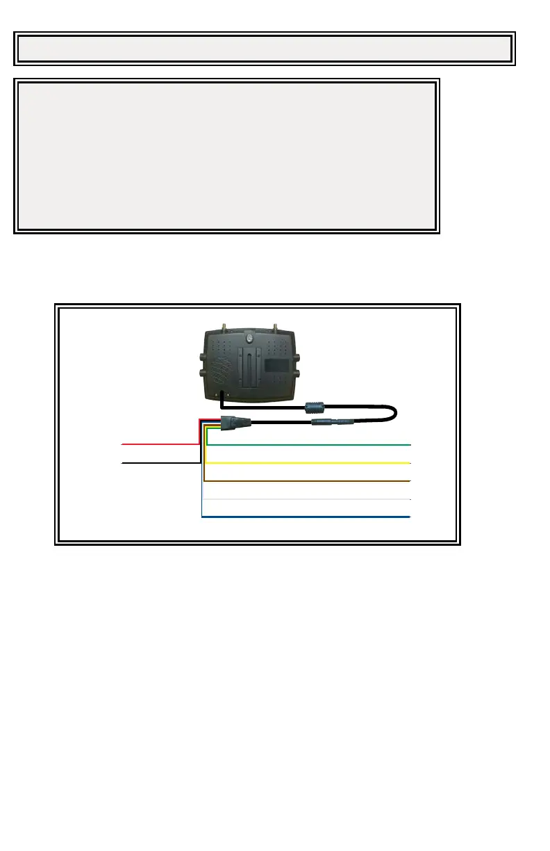
The unit is designed for electrical systems from 12 to 24 VDC (10 to 30 VDC extremes). Wiring options are as follows in Figure 8:
All wiring should be a minimum of 26 AWG. A 3-amp fuse in the positive line for the monitor is required.
SD card (Keys provided)
ECANTE-5ECANTE-5
Power (RED)
Ground (BLACK)
Camera #1 - Optional trigger (GREEN)
Optional trigger wire, user selected split/quad view (YELLOW)
Camera #2 - Optional trigger wire (GREY)
Camera #3 - Default reversing, optional trigger wire (BLUE)
EC7008-WM
8 Pin
Camera #4 - Optional trigger wire (BROWN)
PCY-EC7008-WM
EC7008-WK
Figure 8
Important! Waterproof all connections whether inside or outside the vehicle by using sealant and wrapping with insulation tape. Wrap tape tightly,
overlapping by one-half widths so there are no gaps.