13
Description
Description
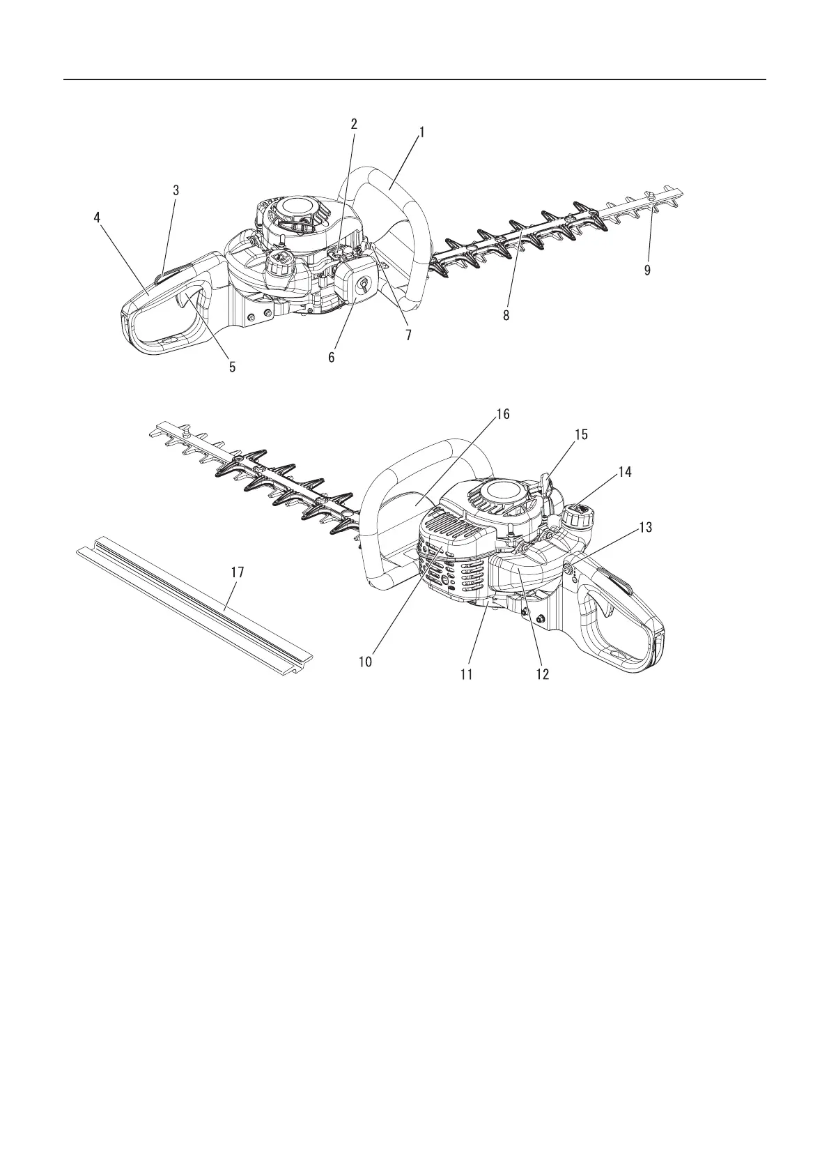
1. Front handle Handle located on the cutting device.
2. Carburettor Device for mixing fuel and air in the correct
proportions.
3. Throttle trigger lockout Device that prevents the acci-
dental operation of the throttle trigger until manually re-
leased.
4. Rear handle Handle located furthest from the cutting de-
vice.
5. Throttle trigger Device activated by the operator's finger,
for controlling the engine speed.
6. Air cleaner cover Covers air filter.
7. Spark plug
8. Blunt extension An extending blunt part of the cutting de-
vice. (Applicable to double edged blade unit)
9. Cutting device That part of the assembly of cutter blade
and shear plate together with any supporting part, which
performs the cutting action.
10. Silencer cover Cover for the silencer to prevent operator
contact with hot exhaust.
11. Gear housing Housing to support the gears that reduce
the speed of engine to cutting attachment.
12. Fuel tank Contains fuel and fuel filter.
13. Ignition switch Device for allowing the engine to be
started and stopped.
14. Fuel tank cap For closing the fuel tank.
15. Starter handle Pull handle to start the engine.
16. Guard Guard between the front handle and cutting de-
vice for protecting the hand from injuries if the hand slips
off the handle.
17. Blade cover When transporting or storing the product al-
ways fit the blade cover.