GRASS TRIMMER/BRUSH CUTTER
OPERATOR'S MANUAL
13
ASSEMBLY
POWER
HEAD SHAFT/LOWER SHAFT ASSEMBLY
Tools Required: None
Parts Required: Split Boom Attachment Assembly
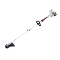
1. Set Power Head/Shaft Assembly on a level surface.
2. Pull locator pin (A) out, and turn counter-clockwise 1/4 turn to lock-
out position.
3. Remove cardboard spacer, if necessary.
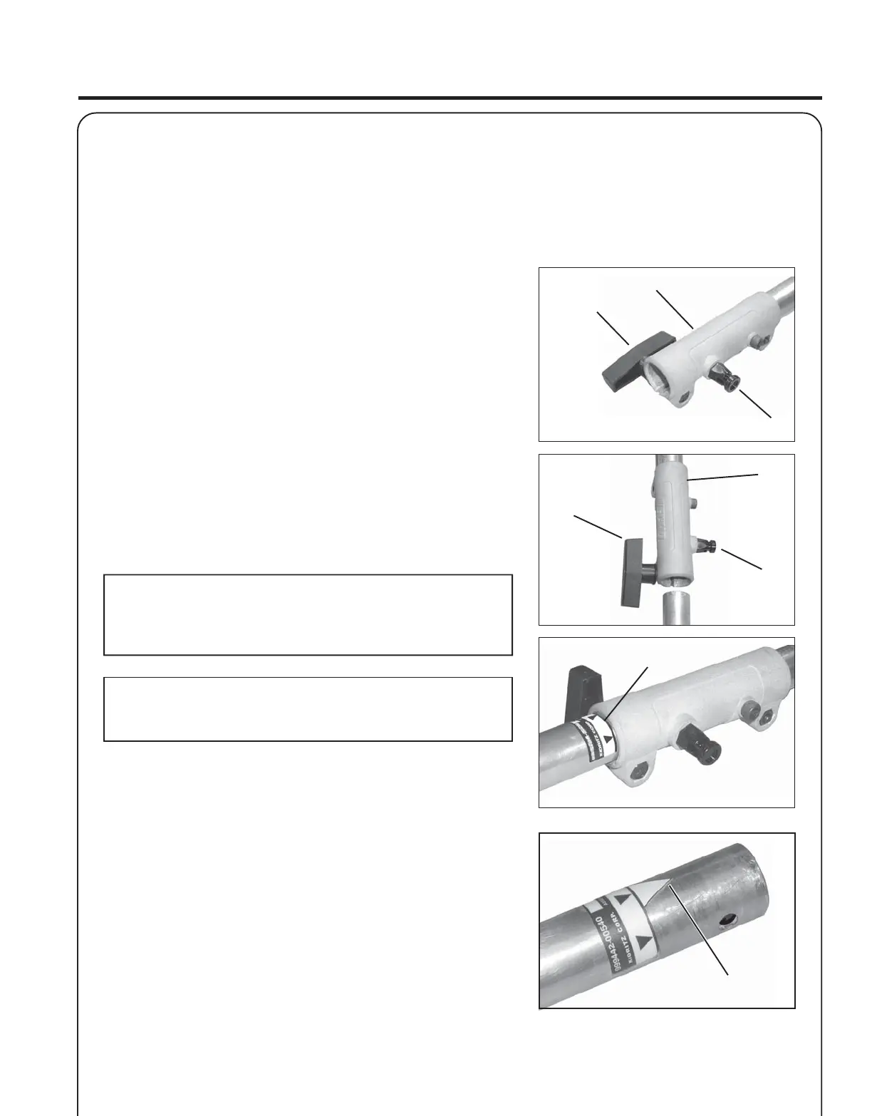
3. Carefully fit attachment drive shaft assembly into coupler (B) to
decal assembly line (C), making sure that the inner lower drive shaft
engages the square upper drive shaft socket.
NOTE
Earlier model Power Heads may have shorter couplings. Short
couplings fit flush to decal point (E). New couplings are 4-3/4 in.
long, and fit flush to line (C).
NOTE
Lower bearing housing and head assembly must be in line with the
engine.
4. Rotate locator pin (A) 1/4 turn clockwise to engage lower shaft
hole. Insure locator pin is fully engaged by twisting lower drive
shaft. Locator pin should snap flush in coupler. Full engagement will
prevent further shaft rotation.
5. Secure lower shaft assembly to coupler by tightening clamping
knob (D).
D
A
A
B
D
C
B
E