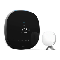
3. Attach the front cover of the Smart Thermostat to the
backplate. Ensure the four pins on the circuit board mate
with the terminal block on the backplate as shown below.
Connecting power
Once you’ve completed the wiring of the Smart
Thermostat and Equipment Interface, you can apply
power to the Equipment Interface and restore power
to the heating and air conditioning equipment.
There are two methods of powering the Smart
Thermostat. You can power it directly from a 24VAC
source capable of at least 3VA.
The second method requires the optional 120V to 12Vdc
power adaptor. Plug the power supply into a standard
electrical outlet and plug the barrel connector into the
Equipment Interface.
Replace the front cover ensuring the pins meet the terminals
Plug the adaptor into the Equipment Interface
Hard-wired 24 VAC option
24 Vac
24Vac | 3VA min
17 Installing The Smart Thermostat
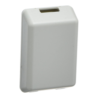
Equipment Interface Status LED
The Equipment Interface has four LEDs to display the
status of the system.
If you’ve wired the system correctly, only the Power LED
should be on.
The LEDs operate as follows:
Power This LED monitors the power supply of the
Equipment Interface.
LED ON Power is connected to the Equipment
Interface and is within the appropriate
voltage range.
LED OFF Power is disconnected or has dropped
below 9V.
System This LED monitors the operation of the
Equipment Interface.
LED ON There is a fault with the Equipment Interface.
LED OFF The equipment interface is operational.
Line This LED monitors the power supplied to the Smart
Thermostat from the Equipment Interface.
LED ON The voltage at the +12V and GND terminal
has dropped below 7V.
LED OFF Adequate power is being supplied to the
Smart Thermostat.
Communication This LED monitors the communication
between the Smart Thermostat and the Equipment
Interface (i.e., the D+ and D- terminals).
LED ON The Equipment Interface and Smart Thermostat
are not communicating with each other.
LED OFF The two devices are communicating properly.
LED arrangement
Power
System
Line
Communication
Installing The Smart Thermostat 18

 Loading...