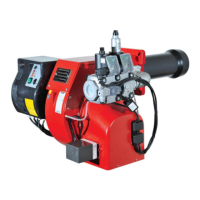
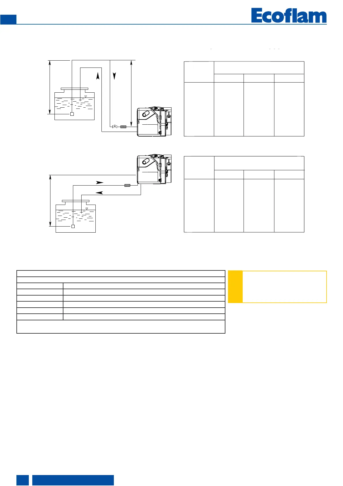
N.B. = X < 20 m
Y must be kept as lower as possible in order to avoid cavitation. Anyway Y< 4 m.
Installation - Oil feeding and suction line
Burner lower than tank
Burner higher than tank
Length pipe (m)
Length pipe (m)
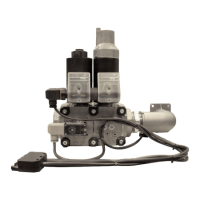
FEEDING LINE WITH DANFOSS BFP11 R3
Correction of altitude
Pump in suction (H +) or charging (H -)
Altitude (m) Theoretical H (m)
0-500 0
501-800 0,5
801-1300 1,0
1301-1800 1,5
1801-2200 2,0
e.g.: altitude 1100m Theoretical H = 1m actual H 2m, Corrected H for suction 2 + 1 = 3m Corrected H for charging 2 - 1 = 1m.
Choose the Ø of the piping from the table, based on the length expanded between the tank and pump. If corrected H for suction
exceeds 4m; make provisions for a transfer pump (max. pressure 2 bar).
!
The length of the tubes apply to
burners powered by 50 Hz mains
electricity; in case of 60 Hz power,
divide the relevant lengths by 1.5.

 Loading...