EasyManua.ls Logo

Ecoflam BLU 1500.1 PAB User Manual

Ecoflam BLU 1500.1 PAB
80 pages
To Next Page IconTo Next Page
Page #1 background imageLoading...
Page #1 background image
Technical data
Dati tecnici
Données techniques
Datos técnicos
Технические характеристики
Technische Daten
Operating instructions
Istruzioni per l’uso
Notice d’emploi
Manual de uso
Руководство по эксплуатации
Betriebsanleitung
Electric diagrams
Schemi elettrico
Schémas électrique
Esquemas eléctrico
Электрические схемы
Elektro Schalt- und Anschlussschemata
Spare parts list
Parti ricambi
Pièces de rechange
Piezas de recambio
Запчасти
Ersatzteilliste
GAS BURNERS
EN
IT
FR
ES
RU
BLU 1500.1 PAB
BLU 1700.1 PAB
BLU 2000.1 PAB
BLU 1500.1 PAB TC 3144001
BLU 1500.1 PAB TL
BLU 1700.1 PAB TC 3144474
BLU 1700.1 PAB TL
BLU 2000.1 PAB TC 3144459
BLU 2000.1 PAB TL
www.ecoflamburners.com
DE
18-01-2016

Other manuals for Ecoflam BLU 1500.1 PAB

Question and Answer IconNeed help?

Do you have a question about the Ecoflam BLU 1500.1 PAB and is the answer not in the manual?

Ecoflam BLU 1500.1 PAB Specifications

General IconGeneral
BrandEcoflam
ModelBLU 1500.1 PAB
CategoryBurner
LanguageEnglish

Summary

Technical Data

Working Fields

Explains the burner's operating field as a function of combustion chamber pressure.

Dimensions

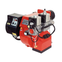
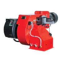
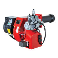
Provides dimensional drawings and specifications for the burner models.

General Warnings

Important Notes

Provides crucial information regarding safe operation and compliance with standards.

Burner Description

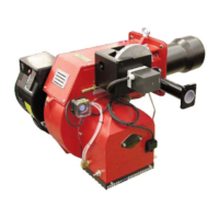
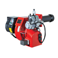
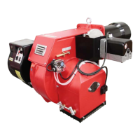
Details the BLU series as two-stage, automatic, monoblock burners with low-polluting combustion.

General Safety Functions

Description of Functions

Outlines the operational sequence, pre-ventilation, and monitoring of burner functions.

Safety Functions

Details critical safety mechanisms including flame failure and lack of air shutdown.

Siemens Control and Safety Unit

Connection Diagram and Control Sequence

Illustrates the wiring and operational sequence of the Siemens LME22 control unit.

Control Panel

Identifies components and functions of the burner's control panel.

Burner Assembly and Installation

Burner Assembly

Instructions for fixing the burner to the boiler and its removal.

Blast Tube Insertion and Brickwork

Guidance on blast tube insertion depth and required brickwork for installation.

Electrical Connection and Checks

Electrode Positioning

Ensuring correct placement of ionisation probe and ignition electrode.

Electrical Connection

Details on authorised electrical installation and connection requirements.

Pre-Commissioning Checks

Comprehensive checklist before initial burner operation.

Burner Output Adjustment

Gas Train Installation and Setting

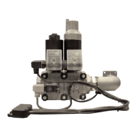
Steps for installing and setting the gas train for PAB version burners.

High Flame Adjustment

Procedure for adjusting gas capacity in high flame mode.

Low Flame Adjustment

Procedure for adjusting gas capacity in low flame mode.

Firing Head Setting

Adjusting the firing head position for optimal combustion efficiency.

Air Pressure & Gas Pressure Settings

Air Pressure Switch Calibration

Steps for calibrating the air pressure switch for combustion air fan monitoring.

Minimum Gas Pressure Switch

Setting the minimum gas pressure switch for correct burner operation.

Burner Maintenance

Exhaust Gas Temperature Check

Procedure for checking and cleaning the boiler based on flue gas temperature.

Burner Maintenance Tasks

List of tasks for maintaining the burner, including checks and cleaning.

Troubleshooting Guide

Fault Diagnosis and Repair

Initial checks and a table for diagnosing and repairing malfunctions.

Annual Maintenance

Recommended annual checks for burner components and parameters.

Gas Pressure Loss Diagrams

Natural Gas Pressure Loss Data

Table detailing gas train, governor, filter, and pressure loss for natural gas.

LPG Pressure Loss Data

Table detailing gas train, governor, filter, and pressure loss for LPG.

Electric Diagrams

Control Box Wiring

Wiring diagram for the Siemens LME 22 control box.

Servomotor Wiring

Wiring diagram for the Siemens SQN 72.2A4A20 servomotor.

Spare Parts List - BLU 1500.1 P AB

BLU 1500.1 Exploded View

Diagram showing exploded view of the BLU 1500.1 burner components.

Spare Parts List - BLU 1700.1 / 2000.1 P AB

BLU 1700.1/2000.1 Exploded View

Diagram showing exploded view of BLU 1700.1 and 2000.1 burner components.

Spare Parts List - Component Details

Component Descriptions and Codes

List of spare parts with descriptions, designations, and codes for BLU 1500.1 PAB.

Spare Parts List - Russian Component Details

Russian Component Descriptions and Codes

List of spare parts with Russian descriptions, designations, and codes for BLU 1500.1 PAB.

Spare Parts List - BLU 1700.1/2000.1 Component Details

Component Descriptions and Codes (BLU 1700.1/2000.1)

List of spare parts with descriptions, designations, and codes for BLU 1700.1/2000.1 PAB.

Spare Parts List - Russian Component Details (BLU 1700.1/2000.1)

Russian Component Descriptions (BLU 1700.1/2000.1)

List of spare parts with Russian descriptions, designations, and codes for BLU 1700.1/2000.1 PAB.

Conformity Declaration

Declaration of Conformity for Gas Burners

Ecoflam Bruciatori S.p.A. declares conformity of BLU gas burners to relevant standards.

Related product manuals