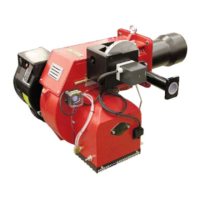
Do you have a question about the Ecoflam BLU 8000.1 PR and is the answer not in the manual?
States compliance with standards and directives for Ecoflam gas burners.
Explains how gas burners and gas trains are supplied, and available kits.
Details the functions of the control panel indicators and buttons.
Describes gas train components, kits, and their assembly to the burner.
Lists gas categories applicable to different countries for the burners.
Shows burner output vs. pressure and flame dimensions based on output.
Details fixing hole dimensions and installation considerations for the mounting flange.
Describes the burner's start-up sequence and safety checks.
Explains how the burner operates in partial and full-load stages.
Details 2-stage sliding and stepless control for gas and air flow.
Covers safety shut-off procedures and indicators for various fault conditions.
Instructions for physically installing the burner into the boiler.
Pre-installation checks for burner lining and electrode settings.
Shows the connection diagram for gas trains with separate pilot systems.
Covers valve groups, pressure, leak testing, venting, support, and joints.
Details pilot gas train connection and head loss diagram for combustion head.
Provides diagrams for pressure drop of gas trains, governors, and filters.
Covers applicable standards, burner and gas train connections, and probe connections.
Lists checks required before starting the burner for the first time.
Details the step-by-step process for starting the burner on gas.
Explains how to calculate gas flow rate and related parameters.
Discusses secondary air effects and recommended combustion parameters.
Guides on setting the maximum air flow rate for optimal combustion.
Explains the adjustment of the firing head for burner output.
Details the pre-setting of the servomotor for air damper control.
Instructions for adjusting the burner's intermediate capacity using cams.
Procedures for calibrating air and gas pressure switches.
Final adjustments to the servomotor cams for minimum output.
Lists recommended tasks for annual burner maintenance.
Provides a method to calculate exhaust gas loss based on parameters.
Guides on removing blast tube, firing head, and cleaning gas filters.
A table listing causes, remedies, and symptoms for gas operation faults.
Explains fault indications and the control box program behavior during trouble.
Details the functionality of control boxes and damper actuators.
Provides wiring diagrams for various burner components and configurations.
Lists part numbers and descriptions for burner components.
